BuddytheReow
Breadboard Baker
Hi Everyone! Welcome to "The Test Kitchen"! If you've opened this thread it probably means you're thinking one of two things: "What the heck is 'The Test Kitchen' and/or 'I'm kinda new around here and would love to brush up on my circuit knowledge/building skills'". Here is a great place to start on your new adventure of breadboarding!!
What is a breadboard?
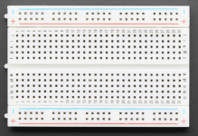
A solderless breadboard is widely considered the most versatile prototyping platform for circuit building. They come in various sizes and colors, but they all function in the same way. Here is what a typical breadboard looks like:

How does a breadboard work?
The screenshot below is taken from beavisaudio.com. Starting on the outer edges you will see two holes with colors next to them. Typically, these colors are red and blue and indicate the direction the electricity flows when power is connected to them. Red is typically used for positive voltage and Blue is typically used for ground. You can alter this to have negative voltage, but that is a topic for another day once you've got the basics down. When power is connected to one of the holes in the colored strip seen below, all of the vertical holes in that strip will have power since they are all connected underneath the plastic shell. If you want power/ground on both sides of the board you will have to use jumper cables. More on that in a moment.
Moving to the inner section where you see letters on the edges of the board, each of the 5 horizontal holes are connected across columns A through E and separately from F through J. Rows 1 and 2 for example are not connected to each other, but jumper wires can fix that if needed.

In between columns E and F is a canal that separate the board into 2 mirror-like sections. This provides 2 separate sections of your board to work with that are relatively close to each other. The other advantage of this is to separate the pins on various Integrated Circuits (ICs or IC chips) into individual rows like so...

You keep saying 'Jumper Wires'. What are they?
These are jumper wires. They come in various colors, sizes, and thicknesses. They are used to connect one row to another in series. You can also connect power/ground to a certain row on your board or you can link the power/ground to the other side of the board. If you look 2 screenshots up you will see a blue and red line going from left side of the board to the right side. Those represent jumper cables. If you're looking to buy them just google "breadboard jumper wires". Without the term "breadboard" you will probably find cables for your car. You don't want those .
.

OK. I kind of understand what a breadboard is now. Why do I need one?
Good question! As mentioned above, a breadboard is a platform for solderless prototyping. Let's look at those two words.
Solderless
All of the circuit boards for sale at PedalPCB.com require some soldering skills. While soldering is not inherently difficult, it does take a little bit of practice and some tools/supplies. Solder can really only be used one time and is considered to be a "more permanent" connection; a breadboard can be reused many times and is considered a "less permanent" connection. The leads of you components will need to be bent in order to stick it in the hole like this if you have leads that come out of both sides of your component.

If you have components that have leads coming out of only one side (such as a capacitor or a transistor) you may only need to bend the leads slightly to space them out to fit into the board like this.

Prototyping
This is where a lot of the fun and/or learning comes into play. For me, both words are used. To use a breadboard you will HAVE to learn how to read a schematic and there will (hopefully in time) be a separate thread on how to do so along with some step-by-step instructions for some of the more simple circuits out there. Being able to translate a schematic to your breadboard will help you understand what is happening in any given circuit.
Experimenting! This is where all breadboarders have their fun. If you are looking at your breadboard with a wired up circuit you may then get the urge to "tinker" with it and, by golly, you should! What happens to the sound of my guitar effect if I change this resistor/capacitor/transistor/IC/diode, etc. for a different one? What happens if I add a tone stack to this or an extra gain stage or an extra set of diodes? Well, try it and find out! Sometimes you will get positive results, and other times you will get something that sounds like crap. Sometimes you may not get ANY sound coming out! Try it and see! If you've been circling around the other posts on this website you will notice a lot of people say to "socket" certain components to find out what someone likes best. A breadboard is nothing BUT sockets! Experiment until you've received religious fulfillment!!
A breadboard sounds too good to be true! Are there any downsides to using this?
While it may seem like a breadboard is virtually a godsend into the electronics community, there are definitely some downsides to using this. Here are some of them.
-Breadboards wear out. Over time, after putting components in and out of those holes dozens, hundreds, and (if your lucky) thousands of times, your breadboard will eventually wear out. The board may not grip the component correctly or the connecting metal strip directly beneath the hole will stop connecting. This is inevitable. The good news is that breadboards are pretty cheap and can be found at many electronics hobby stores or the good 'ole internet.
-Breadboard made circuits can and do get messy faster than you may realize! Breadboard circuits are not as neat as the schematics. Ran out of room on a certain strip? Well, lets move the rest of that circuit block with a jumper wire to a different area and them add another jumper wire back to complete the block. If you're not careful with how you lay out your circuit it will start to look like a plate of spaghetti. If/when you have to troubleshoot a circuit on your board it will be harder to figure out where everything is going. Below is an example of only a few components used, but the jumper wires make it really messy. The best solution is to use the shortest jumper wires as possible to cut back on SOME of the mess.

-Breadboards can get noisy. If you like building pedals, and all of us here on this site do, nearly all of our PCBs go into a metal enclosure. This metal enclosure serves 3 purposes: it protects the circuit from accidentally getting stepped on, the enclosure provides a whole other platform of visual artistic expression, and protects the circuit from most other electronic interference. Using a breadboard does not allow us the benefit of the first and third items. You are welcome to try the second one and draw something cool on your breadboard, but don't come crying when you accidentally got paint in the breadboard holes. Because we have no grounding protection around the actual circuit the breadboard can sometimes act like an antenna and accidentally pick up a lot of unwanted noise like stray radio waves or from your overhead fluorescent lighting. High gain circuits can hum a lot too on a breadboard. Jumper cables can also add to this problem as well. As mentioned above, always use the shortest jumper wire possible to keep this to a minimum.
-Breadboards require offboard components in order to work.
First, you're going to need to power the darned thing. You can either hook up a battery to the power strips or use a DC power plug.
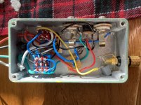
Want to be able to adjust the gain, volume, tone, speed, etc? You're gonna have to get a potentiometer hooked up to your board somehow. If you've got a pot with PCB pins on them it is NOT advised to mash it into your breadboard. You will definitely damage the board. The best bet is one of two options: either build a daughterboard where you can change your pots out and add some jumper wires OR you can solder some solid core wire onto the individual pot legs and shove those into your breadboard. The downside to both is that you'll be adding more spaghetti/mess to your board. Switches and their problems are similar too. Find the method that works best for you.
You still need to get your guitar/bass signal both into and out of the board into your amp. Those input/output jacks have to be used too.
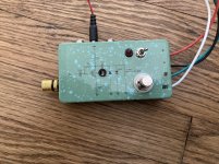
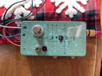
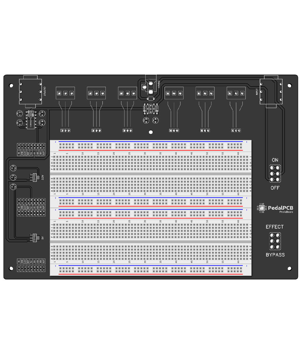
There are 2 solutions to the offboard components problem: you can either build yourself a "guitar effect test box" (just google it) or you can go to the Utility section of the PedalPCB website and buy yourself a Protoboard or Protoboard Micro
This all sounds great. You've been very helpful. I'm going to buy my first breadboard and get started!
Great to hear! I hope I was able to shed some light on some of the mystery behind the breadboard. With some patience, circuit knowledge, components, and a little bit of luck, you will be able create some wonderful and fascinating sounds worthy of some of the guitar greats! If anyone has any other "Breadboarding 101" knowledge or insights please feel free to contribute. The more we learn from each other the better!
Thanks,
BuddyTheReow
What is a breadboard?
A solderless breadboard is widely considered the most versatile prototyping platform for circuit building. They come in various sizes and colors, but they all function in the same way. Here is what a typical breadboard looks like:
How does a breadboard work?
The screenshot below is taken from beavisaudio.com. Starting on the outer edges you will see two holes with colors next to them. Typically, these colors are red and blue and indicate the direction the electricity flows when power is connected to them. Red is typically used for positive voltage and Blue is typically used for ground. You can alter this to have negative voltage, but that is a topic for another day once you've got the basics down. When power is connected to one of the holes in the colored strip seen below, all of the vertical holes in that strip will have power since they are all connected underneath the plastic shell. If you want power/ground on both sides of the board you will have to use jumper cables. More on that in a moment.
Moving to the inner section where you see letters on the edges of the board, each of the 5 horizontal holes are connected across columns A through E and separately from F through J. Rows 1 and 2 for example are not connected to each other, but jumper wires can fix that if needed.
In between columns E and F is a canal that separate the board into 2 mirror-like sections. This provides 2 separate sections of your board to work with that are relatively close to each other. The other advantage of this is to separate the pins on various Integrated Circuits (ICs or IC chips) into individual rows like so...
You keep saying 'Jumper Wires'. What are they?
These are jumper wires. They come in various colors, sizes, and thicknesses. They are used to connect one row to another in series. You can also connect power/ground to a certain row on your board or you can link the power/ground to the other side of the board. If you look 2 screenshots up you will see a blue and red line going from left side of the board to the right side. Those represent jumper cables. If you're looking to buy them just google "breadboard jumper wires". Without the term "breadboard" you will probably find cables for your car. You don't want those
.
OK. I kind of understand what a breadboard is now. Why do I need one?
Good question! As mentioned above, a breadboard is a platform for solderless prototyping. Let's look at those two words.
Solderless
All of the circuit boards for sale at PedalPCB.com require some soldering skills. While soldering is not inherently difficult, it does take a little bit of practice and some tools/supplies. Solder can really only be used one time and is considered to be a "more permanent" connection; a breadboard can be reused many times and is considered a "less permanent" connection. The leads of you components will need to be bent in order to stick it in the hole like this if you have leads that come out of both sides of your component.
If you have components that have leads coming out of only one side (such as a capacitor or a transistor) you may only need to bend the leads slightly to space them out to fit into the board like this.
Prototyping
This is where a lot of the fun and/or learning comes into play. For me, both words are used
. To use a breadboard you will HAVE to learn how to read a schematic and there will (hopefully in time) be a separate thread on how to do so along with some step-by-step instructions for some of the more simple circuits out there. Being able to translate a schematic to your breadboard will help you understand what is happening in any given circuit.Experimenting! This is where all breadboarders have their fun. If you are looking at your breadboard with a wired up circuit you may then get the urge to "tinker" with it and, by golly, you should! What happens to the sound of my guitar effect if I change this resistor/capacitor/transistor/IC/diode, etc. for a different one? What happens if I add a tone stack to this or an extra gain stage or an extra set of diodes? Well, try it and find out! Sometimes you will get positive results, and other times you will get something that sounds like crap. Sometimes you may not get ANY sound coming out! Try it and see! If you've been circling around the other posts on this website you will notice a lot of people say to "socket" certain components to find out what someone likes best. A breadboard is nothing BUT sockets! Experiment until you've received religious fulfillment!!
A breadboard sounds too good to be true! Are there any downsides to using this?
While it may seem like a breadboard is virtually a godsend into the electronics community, there are definitely some downsides to using this. Here are some of them.
-Breadboards wear out. Over time, after putting components in and out of those holes dozens, hundreds, and (if your lucky) thousands of times, your breadboard will eventually wear out. The board may not grip the component correctly or the connecting metal strip directly beneath the hole will stop connecting. This is inevitable. The good news is that breadboards are pretty cheap and can be found at many electronics hobby stores or the good 'ole internet.
-Breadboard made circuits can and do get messy faster than you may realize! Breadboard circuits are not as neat as the schematics. Ran out of room on a certain strip? Well, lets move the rest of that circuit block with a jumper wire to a different area and them add another jumper wire back to complete the block. If you're not careful with how you lay out your circuit it will start to look like a plate of spaghetti. If/when you have to troubleshoot a circuit on your board it will be harder to figure out where everything is going. Below is an example of only a few components used, but the jumper wires make it really messy. The best solution is to use the shortest jumper wires as possible to cut back on SOME of the mess.
-Breadboards can get noisy. If you like building pedals, and all of us here on this site do, nearly all of our PCBs go into a metal enclosure. This metal enclosure serves 3 purposes: it protects the circuit from accidentally getting stepped on, the enclosure provides a whole other platform of visual artistic expression, and protects the circuit from most other electronic interference. Using a breadboard does not allow us the benefit of the first and third items. You are welcome to try the second one and draw something cool on your breadboard, but don't come crying when you accidentally got paint in the breadboard holes
. Because we have no grounding protection around the actual circuit the breadboard can sometimes act like an antenna and accidentally pick up a lot of unwanted noise like stray radio waves or from your overhead fluorescent lighting. High gain circuits can hum a lot too on a breadboard. Jumper cables can also add to this problem as well. As mentioned above, always use the shortest jumper wire possible to keep this to a minimum.-Breadboards require offboard components in order to work.
First, you're going to need to power the darned thing. You can either hook up a battery to the power strips or use a DC power plug.
Want to be able to adjust the gain, volume, tone, speed, etc? You're gonna have to get a potentiometer hooked up to your board somehow. If you've got a pot with PCB pins on them it is NOT advised to mash it into your breadboard. You will definitely damage the board. The best bet is one of two options: either build a daughterboard where you can change your pots out and add some jumper wires OR you can solder some solid core wire onto the individual pot legs and shove those into your breadboard. The downside to both is that you'll be adding more spaghetti/mess to your board. Switches and their problems are similar too. Find the method that works best for you.
You still need to get your guitar/bass signal both into and out of the board into your amp. Those input/output jacks have to be used too.
There are 2 solutions to the offboard components problem: you can either build yourself a "guitar effect test box" (just google it) or you can go to the Utility section of the PedalPCB website and buy yourself a Protoboard or Protoboard Micro
This all sounds great. You've been very helpful. I'm going to buy my first breadboard and get started!
Great to hear! I hope I was able to shed some light on some of the mystery behind the breadboard. With some patience, circuit knowledge, components, and a little bit of luck, you will be able create some wonderful and fascinating sounds worthy of some of the guitar greats! If anyone has any other "Breadboarding 101" knowledge or insights please feel free to contribute. The more we learn from each other the better!
Thanks,
BuddyTheReow

 built/still use. Was inspired by the tagboard post since I chose to use alligator clips rather than a speaker terminal. I simply use a jumper wire from the board to the alligator clip. Saves a lot of time trying to ground the jacks, etc