
mkstewartesq
Well-known member
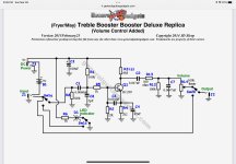
This kit is essentially a modern treble booster. However, once finished, I discovered it is actually attenuating, not boosting the signal. At first I thought it was just a week booster but then I noticed that, when playing through an overdriven amp, it was actually cleaning the sound up; when played through a clean amp, the sound becomes almost in audible and comes in and out almost like a tremolo.
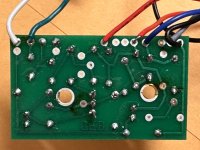
Background: boy, I felt five or six boards from PedalPCB, Aion, etc. but this one was decidedly more old-school than I was a custom to. Fairly minimalist board and some truly weird (to me) offboard wiring - i.e., solder tacking a resistor and a capacitor directly onto the potentiometer, soldering a capacitor between two resistors on the board, etc. The board also seemed a little weird. In my pics you will see scorch marks – this board had a lot of space is that word to be left empty and, somehow, solder always seem to magically pop up in those holes so I had to remove it. Never had that issue with any other board.
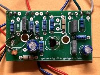
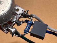
In any event, I am attaching the schematic, pictures of the front and back of the board, and pictures of the potentiometer with the weird solder tacking on it. (I also tried the pedal without the resistor and capacitor on the potentiometer and it didn’t really make a difference to the sound).
The transistor is a BC 239 A - the voltages I am getting appear to be in the desired range; specifically I am getting the following values (using the red lead on the multimeter they all read as negative; when I use the black lead, they show as positive):
C: -6.5 V
B: -1.6 V
E: -1.01 V
Since you are seeing the pictures, I will also include the (rather vague) notes about the weird offboard wiring if that helps you determine that that might be the issue.
“There is some off-board wiring for R12 and C7. These components need to be solder tacked between lugs 3 and 1 of the volume control. Probably the easiest way to do this is to solder the resistor between the pot lugs and then solder tack the capacitor parallel onto the resistor.
C8 will need to be solder tacked between the ground point on the leg of R8 and the inside end of R1”
Any thoughts appreciated. Thank you,
Mike
Background: boy, I felt five or six boards from PedalPCB, Aion, etc. but this one was decidedly more old-school than I was a custom to. Fairly minimalist board and some truly weird (to me) offboard wiring - i.e., solder tacking a resistor and a capacitor directly onto the potentiometer, soldering a capacitor between two resistors on the board, etc. The board also seemed a little weird. In my pics you will see scorch marks – this board had a lot of space is that word to be left empty and, somehow, solder always seem to magically pop up in those holes so I had to remove it. Never had that issue with any other board.
In any event, I am attaching the schematic, pictures of the front and back of the board, and pictures of the potentiometer with the weird solder tacking on it. (I also tried the pedal without the resistor and capacitor on the potentiometer and it didn’t really make a difference to the sound).
The transistor is a BC 239 A - the voltages I am getting appear to be in the desired range; specifically I am getting the following values (using the red lead on the multimeter they all read as negative; when I use the black lead, they show as positive):
C: -6.5 V
B: -1.6 V
E: -1.01 V
Since you are seeing the pictures, I will also include the (rather vague) notes about the weird offboard wiring if that helps you determine that that might be the issue.
“There is some off-board wiring for R12 and C7. These components need to be solder tacked between lugs 3 and 1 of the volume control. Probably the easiest way to do this is to solder the resistor between the pot lugs and then solder tack the capacitor parallel onto the resistor.
C8 will need to be solder tacked between the ground point on the leg of R8 and the inside end of R1”
Any thoughts appreciated. Thank you,
Mike
Attachments
Last edited: