Fun with the Electra

MBFX

Well-known member
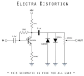
The Electra circuit is really easy to build, makes a lot of gain, seems to not care about which transistor you use, and is also a good boost with a lot of color if you skip the clipping diodes, so it's perfect for a beginner like me.

I had an idea of making an Electra with a selectable clipping section, but the volume cut when the diodes were engaged made me sad. I decided to make another Electra boost circuit that fed into them, with a different resistor ratio in the voltage divider section to make the gain match.

I thought it worked, but I had actually done something a little different. I made a booster into a booster, and the diodes weren't doing anything. Going to report back 😂
 
Last edited:
OK, so here is my intention. When adding clipping diodes, output is decreased. I want to make that output decrease go away. I tried sending more signal to the diodes (correctly this time), but that just made the quieter clipping more intense and fuzzy. It sounded great, but not louder. Is there a way to compensate for the volume drop?
 
The diodes will only ever permit their Vf to pass. They'll clip everything else.
More in will never equal more out with hard clipping.

Try adding resistance to ground in the no clipping position to level match the clipping selections.
You can start with a pot or trimmer and match by ear, measure the selected resistance then swap for a resistor.

You can also add resistance between the signal and diodes(opposite side of ground).
It still want level match though.
 
Best way is to build a recovery stage right after the diodes. Adjust the gain with a pot for the emitter resistor. Changing the diodes will change the volume drop and therefore the gain needed on the recovery stage. It’s just the nature of diodes with different forward voltages.
 
Thank you! That makes sense, trying to match the cut. The recovery stage is what I wanted to do, but I didn't build it properly. I was trying to make a single knob effect - it sounds like I will need two, with one for the booster and one for the recovery stage?

I'm also unsure of how to separate the two sections, if the recovery stage is after the diodes and needs to go to output. Can I just... have two things connected to my output rail?
 
Last edited:
Thank you! That makes sense, trying to match the cut. The recovery stage is what I wanted to do, but I didn't build it properly. I was trying to make a single knob effect - it sounds like I will need two, with one for the booster and one for the recovery stage?
I read it as you want a clipping and non clipping option.
If so, level match and you should be able to get by with a fixed recovery stage. The input of that stage will always be the same-ish peak to peak, if you level match.
Note, it probably won't be level matched if you turn the gain of the first stage way down.
But, if you crank the first stage too much, you'll get needed noise amplification.
I'd recommend reading over and bookmarking these if you haven't already


Yes, exactly! A "clean" (for an old transistor) boost, and a selectable clipping section that doesn't drop the output. I can build a booster, and I can build an Electra, but I am having a lot of trouble figuring out my intended endpoint.

Right now I have a 100K pot coming off the booster, so the output comes from pin 2, and pin 3 goes to ground. I feel like I need to do something different in order to get my intended result, but not sure what.

Maybe what I need to do is make to separate circuits, and switch between them! That would work, at the expense of extra components and a larger board. I'm trying to squeeze all this on 1x1" perfboard
 
In your "clean" non clipping position, use a pot as a voltage divider.
Into pin 2. Out one pin, 3 to ground, or vise versa. Level match the clipping with that.
It's just a resistor to ground but you can tune it to find *what* resistor value you need there.
Once you find the value, you can swap it for a resistor to ground.
 
The 100K is the volume control. I want a fixed amount of clipping (as much as possible).

I am close! I tried feeding the output of the boost to a DPDT like this:
1-----4 to output jack---2 5---from boost out from recovery stage out---3 6---to input cap of recovery stage

I put a 100K pot on the output stage, but that made the input stage impossible to control. I need to connect the 100K where it was on the booster, and then wire up the clipping stage. I'll use a single resistor to control the output of the clipping stage. If I get it working I'll post again!

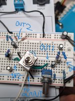
EDIT: I put the 100K back on the input stage, but given where the diodes were the input stage was still controlling the distortion. It sure did get loud, though. I moved the diodes to the output of the recovery stage, and BOOM! Exactly what I wanted! Photo of the breadboard coming
 
Last edited:
PXL_20231029_024212697.jpg

I really like simple circuits the most. One or two knobs, a switch maybe, and the on/off stomp switch. This circuit sounds great! Input stage is a BC108, and the clipping stage is a BC548C.

@BuddytheReow I don't think I built what you suggested, even though it does what I want it to do.

Edit: I reread your post and figured it out. Thanks for the explanation!
 
Last edited:
My solution was to make a 2knobJob with a 4PDT:

96e194c5-755c-4d9c-bafc-5c14fb7dbe33-jpeg.32508


Swaps out two volume pots with LED indication which is on and the extra pole of the 4PDT switches out the diodes.
 
OK, so here is my intention. When adding clipping diodes, output is decreased. I want to make that output decrease go away. I tried sending more signal to the diodes (correctly this time), but that just made the quieter clipping more intense and fuzzy. It sounded great, but not louder. Is there a way to compensate for the volume drop?

I think what I would try is replacing the volume pot with a fixed voltage divider, then using a 2-pole rotary switch with one pole selecting diodes, and the other swapping out a resistor in that voltage divider. Add a recovery stage with a volume control after that for global volume.

You'd need to spend a lot of time fussing with the resistor ratios to get them to match the volume drop from each set of diodes, but you should be able to get it pretty close.
 
Last edited:
That is a really interesting take on things, and it would work well. Would there be any advantage to that, vs. what I have built?
 
I'm not sure I quite follow what you ended up building - can you draw a schematic or at least a block diagram?
 
I think what I would try is replacing the volume pot with a fixed voltage divider, then using a 2-pole rotary switch with one pole selecting diodes, and the other swapping out a resistor in that voltage divider. Add a recovery stage with a volume control after that for global volume.

You'd need to spend a lot of time fussing with the resistor ratios to get them to match the volume drop from each set of diodes, but you should be able to get it pretty close.
This would work nicely if you're ok with not having a volume control. Dealer's choice
 
I'm not sure I quite follow what you ended up building - can you draw a schematic or at least a block diagram?

The diagram of the DPDT switch I posted earlier is the important part. The circuit is two of these, connected via the switch:

1698685289751.png

The first Electra has no diodes, so it's a simple booster. The input jack goes to the input of the first Electra. The output of the first Electra goes to the 100K volume pot, which connectes to lug 5 of the DPDT. Lug 2 of the DPDT goes to the output jack. Lugs 1 and 4 are bridged, so in that switch position, the boost goes straight to the output jack.

On the other side of the DPDT, lug 6 goes to the input of the second Electra. The output of the second Electra goes to lug 3 of the DPDT and the diodes, and Bob's your uncle.

The volume pot is on the end of the first Electra,

EDIT: lug numbers, detail
 
Last edited:
The diagram of the DPDT switch I posted earlier is the important part. The circuit is two of these, connected via the switch:

View attachment 59473

The first Electra has no diodes, so it's a simple booster. The input jack goes to the input of the first Electra. The output of the first Electra goes to the 100K volume pot, which connectes to lug 5 of the DPDT. Lug 2 of the DPDT goes to the output jack. Lugs 1 and 4 are bridged, so in that switch position, the boost goes straight to the output jack.

On the other side of the DPDT, lug 6 goes to the input of the second Electra. The output of the second Electra goes to lug 3 of the DPDT and the diodes, and Bob's your uncle.

The volume pot is on the end of the first Electra,

EDIT: lug numbers, detail
So, it's 2 electras in series with a switch to select the second one with diodes. Is it the second electra you are asking about in terms of volume compensation? Are you considering selectable diodes?
 
I'll preface this by saying that if it sounds good and you're happy then it's good and don't overthink it.

Personally, I would want the clean boost *after* the clipping stage if you're trying to highlight the differences between clipping diodes.

HlXxMSR.png
 
Back
Top