Help needed to wire DPDT to switch input/output a la Gilmour on Vox Wah

ac30irons

Member
Hi all, I hope someone can help.

I have just modded a vox 845 wah to true bypass and installed and led. Success.

I want to be able to switch the input and output with a DPDT to do the Gilmour seagull thing. Does anyone have any idea how to do this. I have tried following an instruction online but it really doesn’t work.

Cheers
 
When you say “switch the input and output” what do you mean? (Since I’m not familiar with the seagull reference, maybe your meaning is clear to those who are.)
 
When you say “switch the input and output” what do you mean? (Since I’m not familiar with the seagull reference, maybe your meaning is clear to those who are.)
So when you flick the switch the input becomes the output and viseversa. The equivalent of unplugging your jacks and switching them.
 
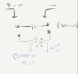
Okay, it’s not that bad. If you look at the bottom of the 2P2T switch, there’s 2 rows of three pins or solder tabs coming off of it. The center tab of each three is connected to the flip flop (not a technical term) and will make contact with the pins opposite whatever side the toggle is on. (This is a bit confusing, but if you think of the toggle as a lever that continues past the top of the switch, when the toggle is pointing down, the extension of it, which has the electrical contact, is pointing up, and making contact with the 2 pins that are on the up direction.)

So you want the input hot lead to attach to one of the end pins, and the output lead to connect to the other pin at that end of the threesome. The center pins (the flip flops mentioned above) get connected to the input and output points on the circuit board. So, if left just like this, when the toggle is pointing away from the connections you just made, it would be like the switch isn’t there. (This would be down, in my sketch above.)

The trick is to now wire up the connectors between the outside pins. For these, all you need to do is cris cross them, so that the input goes to the opposite side, as does the output. This means that when the toggle is pointed the other way, it will contact the pins that reverse what was on the first position of the toggle.

The ground is all connected, and if the board has two ground connection points, just wire it as normal, and if the board has only one connection point, connect the ground of both jacks together, and run that to the board.

Rereading this, I hope I haven’t left you more confused. If I have, pm me and we can set up time to do a quick phone call.
Cheers dude, thanks for your help. So do I remove the board in and out from the true bypass or jump wires from the 3dpdt to the DPDT ?
 
The jack in and out go to the end (outermost) pins on the switch, and from those to the diagonally opposed outermost pins on the other end. The two center pins each get wires going to the 3P2T (stomp switch) locations that the jack in and outs originally went to.
 
Awesome job, @Alan W.

The "seagull" mod has been discussed elsewhere on the PPCB forum, ac30rions, if either you or Alan W have further interest — there's some demos and possibly additional info.
Gotta go to work, will try to find the relevant links later.
 
Awesome job, @Alan W.

The "seagull" mod has been discussed elsewhere on the PPCB forum, ac30rions, if either you or Alan W have further interest — there's some demos and possibly additional info.
Gotta go to work, will try to find the relevant links later.
Thanks, will do a search and see what I can dig up.
 
The jack in and out go to the end (outermost) pins on the switch, and from those to the diagonally opposed outermost pins on the other end. The two center pins each get wires going to the 3P2T (stomp switch) locations that the jack in and outs originally went to.
Bro, you are a legend ! I have just rigged it up like you described and bingo, crazy arsed screaming bird noises at the flick of a switch. Virtual beer 🍺
 
Great that you got it working. Here's a couple links so if anybody stumbles on this thread they can check out the others, too.


Posted in the above thread, Chuck D Bones shared his schematic:

station-wah-cb-mod-png.15910


Robert posted a link to this vid:


In another thread, McNib posted a link to this video:


A brief mention here: #6


I thought there was some more chattering about the seagulls mod, and perhaps there is, but I could only find the above when I searched the forum with Google.
Cheers dude, I may indeed make a fixed Wah version and try and hack in a volume control !
 
Back
Top