Help Wiring 3P4T Rotary Switch

kerryfine

Active member
Hello everyone,

I am getting back into building after a long hiatus. Would anyone be able to help with a diagram on wiring a 3P4T rotary switch to switch between 4 individual PedalPCB circuits, including bypass footswitch and individual LED for each circuit that indicates which is engaged?

With this I'm not sure if there is a way also to avoid a bypass/engaged LED, and instead have it so the LEDs are off when bypassed and then only the single LED of the circuit selected via 3P4T switch lights up.

Thanks for the help,
Kerry Fine
 
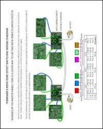
This PDF should give you an indication, here's an example of two rotaries linked together with one of the 4 options for each rotary being bypass:

1703681244203.jpeg

Just wire directly to the rotary switch instead of to the board (or get the Rototone board from GPCB) and then were it me, I would have
input-jack > 3PDT master bypass IN > rotary IN > 4 Effects > rotary OUT > 3PDT Master OUT > output-jack
 
This PDF should give you an indication, here's an example of two rotaries linked together with one of the 4 options for each rotary being bypass:

View attachment 64192

Just wire directly to the rotary switch instead of to the board (or get the Rototone board from GPCB) and then were it me, I would have
input-jack > 3PDT master bypass IN > rotary IN > 4 Effects > rotary OUT > 3PDT Master OUT > output-jack
Thank you for the source but this isn't a 3P4T switch. And again my utilization is to switch between 4 different effects so only one is activated at any given time. I still could use an example with specifically a 3P4T switching between the 4 circuits and with a footswitch bypass, and information regarding the LED situation, to have all LEDs off when bypassed.

What is the SW (switch) terminal on the PCB's? Is that to Ground the switch to prevent popping? How would I wire at terminal on each PCB with the 3P4T?
 
Maybe clarify what you're trying to achieve.


I've re-read the OP, and I still don't see why you need a 3P4T switch when the example I gave can achieve the same result — 4 circuits on a rotary switch, whether you wire up each individual board with a bypass or not, and only one of them is ever on.

If you can only use one circuit at a time, via the rotary, why do you need separate bypasses for each circuit?
Stick a pointy knob on the rotary (such as a Chickenhead) and it'll tell you which circuit is "active" and you'll only need one master LED to indicate whether any of it is "on".
Is it because you have the 3P4T already and don't want to order another switch? (understandable given shipping costs!)


Anyway, I'll see what I can come up with for a 3P4T switch, if anything at all.
 
Just so I understand...

You want a single footswitch to bypass the entire pedal, a rotary switch to select between four different PCBs, and an LED indicator for each PCB that indicates the currently active PCB (and ONLY lit when the 3PDT footswitch is active)?

What is the SW (switch) terminal on the PCB's?

The SW pad is grounded to light the on-board LED.
 
CENTRE-PIN A "IN"outer pins 1, 2, 3, 4Pin 1 > board 1 inPin 2 > board 2 inPin 3 > board 3 inPin 4 > board 4 in
CENTRE-PIN B "OUT"outer pins 5, 6, 7, 8Board 1 out > Pin 5 Board 2 out > Pin 6Board 3 out > Pin 7Board 4 out > Pin 8
CENTRE-PIN C "GND"outer pins 9, 10, 11, 129v > CLR & LED Pin 99v > CLR & LED Pin109v > CLR & LED Pin119v > CLR & LED Pin12


You could do the LEDs the other way round with all the LEDs grounded, and have the CLR-LED combos' anodes connect to 9v on PIN C.
I don't know which way would be better, haven't really thought it through yet.

Also, not sure which is better switch-wise, if it matters at all (might for the LEDs depending on how you wire them:
make before break
or
break before make


Well, that little table was far quicker than me firing up DIYLC.
 
Just so I understand...

You want a single footswitch to bypass the entire pedal, a rotary switch to select between four different PCBs, and an LED indicator for each PCB that indicates the currently active PCB (and ONLY lit when the 3PDT footswitch is active)?


The SW pad is grounded to light the on-board LED.
Yes that is precisely what I am trying to achieve. And thank you for explaining the SW pad.
CENTRE-PIN A "IN"outer pins 1, 2, 3, 4Pin 1 > board 1 inPin 2 > board 2 inPin 3 > board 3 inPin 4 > board 4 in
CENTRE-PIN B "OUT"outer pins 5, 6, 7, 8Board 1 out > Pin 5Board 2 out > Pin 6Board 3 out > Pin 7Board 4 out > Pin 8
CENTRE-PIN C "GND"outer pins 9, 10, 11, 129v > CLR & LED Pin 99v > CLR & LED Pin109v > CLR & LED Pin119v > CLR & LED Pin12


You could do the LEDs the other way round with all the LEDs grounded, and have the CLR-LED combos' anodes connect to 9v on PIN C.
I don't know which way would be better, haven't really thought it through yet.

Also, not sure which is better switch-wise, if it matters at all (might for the LEDs depending on how you wire them:
make before break
or
break before make


Well, that little table was far quicker than me firing up DIYLC.
Ahh thank you so much! Yes I appreciate you taking the time to write that up for me. I don't want to be mindlessly wiring it but I want to be able to conceptualize it while I do it so it makes sense. Thanks again, will be sure to share my results once I wire this thing up, but first need to get my Enclosure designed and ordered! :)
 
Do you need the LED of whatever circuit's selected to be lit up while it's in bypass?
(Handy to know what will be active when you hit the stomper to activate.)

If you prefer no LED's on, then you should tie in the PIN C to the 3PDT's GND.
 
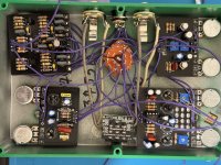
I’ve got the input and outputs wired to the rotary switch, I then used the 3rd section for the “SW” terminal on the boards because I want the switch to also indicate which circuit is engaged, and I want all LEDs off when bypassed. Where do I connect that common terminal on the SW section of the rotary switch?

I also have the boards + and - terminals directly to the DC Jack but I’m wondering if should’ve connected them to the footswitch PCB first or if I can just jump from the DC Jack to the switch?
 

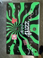
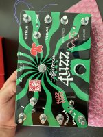
Attachments

  • IMG_7010.jpeg
    IMG_7010.jpeg
    541.8 KB · Views: 5
  • IMG_7014.jpeg
    IMG_7014.jpeg
    464.3 KB · Views: 5
  • IMG_7022.jpeg
    IMG_7022.jpeg
    633.4 KB · Views: 5
Back
Top