
You are using an out of date browser. It may not display this or other websites correctly.
You should upgrade or use an alternative browser.
You should upgrade or use an alternative browser.
How and what to solder in a Perfboard schematic?
- Thread starter delackattack
- Start date
BuddytheReow
Breadboard Baker
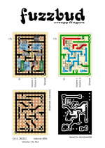
Use the perfboard one even though they’re virtually identical. It’s easier for me to see what connects to what. Ground makes a ring around the whole board. The connections for pots and 9v are inside that ring.
Got a little confused tracing both perfboard ones in my head until I realized the bottom one is reversed which makes sense
Got a little confused tracing both perfboard ones in my head until I realized the bottom one is reversed which makes sense
Feral Feline
Well-known member
Here's the schematic, drawn from storyboardist's layout that you're trying to follow:
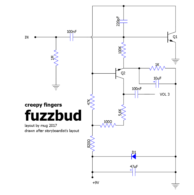
Hope that helps.
Last edited:
delackattack
Member
So the outside lines arent connections?Use the perfboard one even though they’re virtually identical. It’s easier for me to see what connects to what. Ground makes a ring around the whole board. The connections for pots and 9v are inside that ring.
Got a little confused tracing both perfboard ones in my head until I realized the bottom one is reversed which makes sense
Big Monk
Well-known member
This is a great question. I have been very intimidated by the idea of moving beyond PCBs. I could never figure out exactly what to do.
I’ve built in a number of mediums: Strip, Perf, PtP, Terminal Strips, Tag, Vero, etc.
I like PCBs. If I can’t find a PCB, I can design and send away to have it made.
No reason to do anything else.
BuddytheReow
Breadboard Baker
So the outside lines arent connections?

The outside line is one giant connecting loop connecting to ground. The connecting wire to ground is in the bottom right corner. Your other offboard connections go in the holes marked inside this ground "loop". Assuming lug 2 of the volume pot goes to Since this is perfboard you will have to make a solder line all the way around. Other items are connected to it as well, such as the left transistor emitter, part of the 1m pulldown resistor and the negative lead of the 10uf capacitor. Some of the solder "tracks" aren't really necessary since you can use the remaining lead of the component. Take the 4001 diode for example. It's merely there for polarity protection; if you accidentally plug in -9v instead of +9v, the 4001 "activates" and throws all that power to ground. When installing it simply bend the lead all the way to the right and solder the end to the ground "loop". You could do the same thing with the left tranny emitter and the 1m pulldown resistor.
If this is a bit too intimidating you may want to try a stripboard/veroboard layout instead for this found on dirtboxlayouts. https://dirtboxlayouts.blogspot.com/2019/06/creepy-fingers-fuzzbud.html Honestly, I was a little hesitant to start a non-pcb build myself, but it's a pretty simple process. The only difference IMO between building stripboards and PCBs is that you have to "build" your stripboard first. What I mean is that you have to cut the board to size (box cutters, a straightedge, and pliers), cut the breaks in the board (those red boxes and I do them with a drill bit and my fingers. Don't use a power drill since you may go through the board), and solder the connections (black) with either hookup wire or unused leads. One thing to keep in mind is that when making your cuts you will have to do it on the back side of the board since that is where the copper strips are so you will have to mirror the below image accordingly. It's easier for me if I use a sharpie on the top of the board into those holes and flip the board over on a piece of paper. Then you drop your components in exactly as shown (the dark end of the electrolytics 10uf and 47uf is the negative lead). Stripboard is cheap so if you mess up it's no big deal. I would socket the transistors.
The CLR is the current limiting resistor and is done to taste for your LED brightness.

fig
Village Idiot
It's really pretty easy, but a lot more solder than using a printed pcb.
The top right image is color-coded;
Red is Vcc (9VDC)
Blue is the signal path
Green is GND
Place components as shown and solder everything with a line drawn on the backside.
(the bottom images are of the back)
The top right image is color-coded;
Red is Vcc (9VDC)
Blue is the signal path
Green is GND
Place components as shown and solder everything with a line drawn on the backside.
(the bottom images are of the back)
The connections to the hardware are shown as the open dots, but the upper right drawing should not be showing the three dots at the top of the green ground loop.So the outside lines arent connections?
So your 9V wire goes into coordinate BB. Input jack is BL. Ground is JM. Volume 1 and 3 are FL and GL.
I'm assuming Volume 2 goes to the output jack.
The key is making good use of your component leads. For example, I would put the 47uF in place and bend the lead so it reaches the 9V wire. Then put the 820R in place and bend the lead up to the 9V wire. The put the 4001 in place and solder it to the 820R lead that you just bent. So you end up with a nice, tight corner connecting all of those components.
The bottom picture is useful since it shows the underside of the board. You can flip your board over and the "roadmap" should look just like the picture. The white dots show where the component leads are poking through. You can use it to make sure you make the right connections AND didn't accidentally connect two lines that should be separate.
(Dang, Buddy and Fig type faster than me. I need more coffee. Or less coffee. Quite a predicament)
Sturdag Lagernathy
Active member
Perf board is great stuff, and really not hard if you think ahead just a bit. When I was 12, I used to make little transistor multivibrators with an led soldered on a board about the size of a postage stamp. I was making a fake car alarm blinking light that could fit in a cars dash. Gave 'em to all my friends and family. Thought it was so cool.
Feral Feline
Well-known member
What I like to do is to use clipped leads &/or bare wire to run the long lines (*such as the perimeter ground, for example), that way it's not just solder-blobber and I find it takes less solder to make the connections.
 ROG example
ROG examplefig
Village Idiot
I'm always looking for mine. I'd swear someone was moving it if I didn't know better.I need more coffee. Or less coffee. Quite a predicament
@Sturdag Lagernathy just gave me a great idea though....I can build a coffee cup clapper or proximity alarm!
I didn't get the opportunity to explore electronics as a kid...while my parents were still living they had a strict rule about giving me any tools.... it was probably for the best. Now I make the rules, so I ALWAYS place cones around any blast perimeter.
Edit: Good Lord, I read this back and it sounds as if I blew up my parents! No, I did NOT.

Similar threads
- Replies
- 9
- Views
- 283
- Replies
- 9
- Views
- 517