How to make Vero boards

Chuck D. Bones

Circuit Wizard
Here's how I do it. Whether I use my own Vero design or somebody else's, the process is the same. We're going on the assumption that the Vero design has already been checked for correctness. Each step ends with an inspection or test. If anything is wrong, fix it before proceeding to the next step.

1. Mark the Vero board for cutting to size. Recheck the marking. Cut the board to size. I clamp the board in a vise with the line where I'm going to cut just above the jaws. I score the board on both sides and then break it. After that I clean up the rough edges and sharp corners with a grinder. check that the board is the right size and the strips are oriented correctly. I screwed this up once.

2. Mark the board for cutting the strips. I use a fat sharpie. Then I recheck the marking. Keep in mind that most views of the Vero are from the top and the cutting happens on the bottom, so you have to reverse the pattern. I use a drill press with a #28 drill to make the cuts. I set the drill stop so I drill just deep enough to make a clean cut. I used to to it by hand with a pin vise. With a drill press, I can make all of the cuts in the time it took to make just one by hand. Check the board visually to verify all of the cuts are in the right places and there is no conductive debris that could cause shorts. Check each cut with a DMM to ensure the cut is complete.

3. Install the jumpers. Inspect.

4. Install ICs or IC sockets. Inspect.

5. Install resistors. Inspect.

6. Install diodes. Inspect. (notice a trend here?)

7. Install transistors (or sockets). Inspect.

8. Install non-electro caps. Inspect.

9. Install electro caps. Inspect.

10. Perform a thorough inspection of the solder side, looking for shorts between strips.

11. Attach power wires. Install socketed parts. Power it up and check DC voltages.

12. Power off and wire up the rest of the board including switches, pots & jacks. Inspect to make sure all of the wires are in the correct location and there are no shorts where you just soldered. Connect a guitar (or sig gen or looper) to the input, connect and amp or scope to the output and run an end-to-end test. Verify all pots and switches work as expected.

13. Box it & rock it!
 
I put the jumpers in first because sometimes they run under the ICs. I like to put the ICs in next because they are good landmarks for the other parts. I put in the film and electro caps in last because they are easily damaged by an errant soldering iron.

I bend the leads on most parts to retain them. If I can't bend the leads, then I use a bit of painter's tape to hold the parts in.
 
I put the links in first, then the IC socket(s). Then diodes, then resistors, then little caps, then box caps then electrolytic caps. So much like Chuck. I too like to use the IC socket as a reference point. I just hold the part to be soldered in place with my index finger. It just adds to the callus which is already there from playing.
 
Any general tips and tricks on vero?

I've started to try and have the CLR and LED power coming from the vero layout.
Similar with ground, I have multiple ground wires coming off the vero (trying to use the vero as the shared ground). It doesn't look pretty but it's practical..

I started playing around with on-board pots as well (because that will never come back to haunt me if a pot fails) and thinking about the same for LED.
 
I’ve built quite a few vero circuits and would say I’ve been relatively successful other than one particular white whale (the manticore) it works but just doesn’t sound right. Anyways a couple tips that have worked for me.

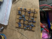
Make a grid on your vero and layout after you cut it. BFBB3AFC-1865-4C93-A145-1792C8A7B5B1.jpeg

For me this makes component placement so much easier. I do it every five lines using a sharpie.

Count your total number of each component and verify the number of components afterwards. I have multiple times had to trouble shoot where I simply didn’t put a resistor or capacitor in that was on the layout.

Inspect inspect inspect and inspect again your soldering. Solder bridges are very easy and it’s much easier to find right after you did it then when it’s finished.

Just because a layout is verified. Doesn’t mean it’s right. There’s a sea machine build on dirtbox layouts for instance verified but the dimension pot won’t work because it’s wrong it will however pass signal and give the effect (ask me how I know)

I would save this for smaller circuits and ones you want to try. The above picture is a the depths clone works awesome after I did some mods to get it to work correctly but I have countless hours into that build. Where as I could have put the pcb together in no time.
 
All great ideas.

Looking back, my first Vero was extremely ambitious. I mounted the pots on-board and became aware of four potential problems:
1. Most Vero boards are single-sided. If you mount the pots on the copper side, like most PC boards, the pots will pull the copper strips off at even the slightest stress.
2. Depending on how you orient the pots (along the strips or across the strips), you could end up having to cut between the holes.
3. The leads on most PCB pots are wide enough that if they are fully seated on the copper side, they will short to an adjacent strip.
4. Although you can run resistors between the pot leads, the gap is small and can damage the resistors, creating shorts. This only happens if the pots are mounted on the component side.

I have had all four of these things give me grief at one time or another.

Mounting the pots on-board will necessitate a much large board.

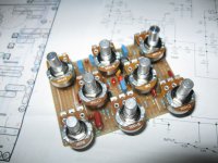
Here's my first Vero. It's an over-the-top BMP. Although it works, it's not that much more versatile than a Way Huge Swollen Pickle. It has true/buffered bypass, a TIGHT control similar to the Brown Betty, a BLEND control (essentially useless), a BIAS control (also of little use), a COMP control similar the Swollen Pickle, TONE & SHIFT controls similar to the Hoof, a TONE SHIFT switch and a GAIN BOOST switch. A fun experiment, and I learned some stuff, but it should have been breadboarded first. As a point of reference, the best BMP I've built (IMHO) is Jason's FuzzDuster.

board 03.jpg
 
Thanks for this! I've been dabbling in some vero builds here and there, so this is very helpful. It's so rewarding when it works and soooo frustrating when it doesn't.

This is probably a super simple, kind of silly question, but how do you go about breaking your board down to size? I have had issues with probably half of my potential boards breaking unevenly and taking a chunk out of the bottom row (which would have been used in the circuit). I'd rather not have to make all my boards one row too big on each side, so I'm curious if you have any tips on breaking them?
 
I prefer the G10 (fiberglass) boards over the phenolic boards. They're stronger, break cleaner, look better and don't absorb moisture. I build with both, but G10 is much better. Break along the holes. Score deeply on both sides with a box cutter knife. Hold the board in a vise with the scored edge just above the jaws. Grab the board firmly just above the scored line and bend it over. Wear gloves. Next time I build a Vero, I'll take pix.
 
I prefer the G10 (fiberglass) boards over the phenolic boards. They're stronger, break cleaner, look better and don't absorb moisture. I build with both, but G10 is much better. Break along the holes. Score deeply on both sides with a box cutter knife. Hold the board in a vise with the scored edge just above the jaws. Grab the board firmly just above the scored line and bend it over. Wear gloves. Next time I build a Vero, I'll take pix.
Awesome, thanks! I'll look into those G10 boards.
 
These are FR4, similar to G10. Good stuff ,but a little more $$ than the phenolic boards Tayda and others sell. StompBoxParts sells Vero boards with plated-thru holes. Not sure what material the board is, but next time I buy some it will be the ones from SBP. Note that SBP sells two types, the difference is the orientation of the strips. Look at the pix on their website to see the difference.
 
I didn't know about VeroRoute. It looks nice (and colorful). I've used DIY Layout Creator (which I learned about from the tagboardeffects site).
 
This is probably a super simple, kind of silly question, but how do you go about breaking your board down to size?

Some boards break easily if you score and bend, but I've also had some thick stubborn ones. I just started using a saw for all of them now. I just drill through the row of holes and it goes quickly, then I sand the side flat (use a mask, you don't want that dust in you).

 
Some boards break easily if you score and bend, but I've also had some thick stubborn ones. I just started using a saw for all of them now. I just drill through the row of holes and it goes quickly, then I sand the side flat (use a mask, you don't want that dust in you).

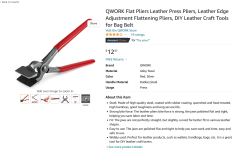
I use one of these sometimes on some of the thicker board. I’ve got a stash of some I got off Amazon that I like and snaps real easy. Its probably lower quality stuff.
 
These are FR4, similar to G10. Good stuff ,but a little more $$ than the phenolic boards Tayda and others sell. StompBoxParts sells Vero boards with plated-thru holes. Not sure what material the board is, but next time I buy some it will be the ones from SBP. Note that SBP sells two types, the difference is the orientation of the strips. Look at the pix on their website to see the difference.
I’ve looked at that and seen people on Reddit mistake it for perf a few times (help my circuit won’t work). Seems like making cuts would be a pita.
 
Back
Top