Hydra tap tempo led

Rpschultz13

Active member
I’m building a Hydra. Was wondering if it’s possible to grab a voltage from somewhere that would look like the delay frequency, like tap tempo.
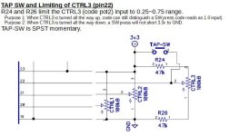
 
The FV-1 doesn't work that way. You need to dig into a specific FV-1 voice patch and set it up to receive a tap-tempo signal from one of the 3 internal pot inputs.

This article on "FV-1 and Tap" over at DIYStompboxes may be a good place to start.

And here's a "Tap-Tempo Code Snippet" from SpinSemi.
 
FV-1 tap tempo (at least the ones I'm familiar with) will count sample periods between button presses then save this value. Then you use that number as the read pointer into delay memory, assuming that your delay buffer starts at address 0, and you have allocated enough memory (32768 is the max). You could also then, e.g. count down to zero and then reset the count with the save value, and send that value to an unused ADC output with a transistor to help drive an LED. I have used this hardware approach to let me visualize LFO speeds. Whether or not that will work with what you are doing I can't say.
 
I’m building a Hydra. Was wondering if it’s possible to grab a voltage from somewhere that would look like the delay frequency, like tap tempo.
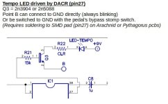
Are you looking for a "circuit only" solution? Or are you able to modify the FV-1 patch(es) to set up a tap-tempo for the Hydra? The patches in the FV-1 will need to be edited to accommodate a tap-tempo input.
 
FWIW, here's everything I have on setting up a tap-tempo for an FV-1 circuit . . .

Circuit Mod TAP.JPG

Circuit Mod Blink LED.JPG

SCALING COMMAND NEEDED TO IMPLEMENT TAP TEMPO IN THE CODE:
scaling command.JPG

And finally, here is a complete "Tap-Tempo Delay" patch code . . . .

;-----INTRO-----
;Phil's tap tempo delay - posted July 2022
;Original inspiration was Babelfish FV-1 Project
;The code has been almost completely re-written with a very different algorithm and more developed features
;The circuit for POT2 tap input and DACR LED --MUST-- follow the correct schematic
;Contact phil.claes.pedals@gmail.com for questions

;-----SPECS-----
;Mono input (ADCL), mono output (DACL)
;Designed to run at 32768Hz
;Tempo LED attached to DACR (with transistor driver)
;Pot 0 = manual time (sets the startup delay time, and detects if you change the pot)
;pot 1 = feedback (# of repeats)
;pot 2 function 1 = tap sw (reads high (value 1) when sw is pressed for tap tempo)
; -Lag is reduced by a high pass filter on the pot2 input in the code
;pot 2 function 2 = lpf of repeats - potentiometer is limited by resistors to 0.25-0.75 range to allow distinguishing sw input.

;-----Set up Registers-----
equ db reg0 ;tap switch debounce time
equ tap_time reg1 ;counts the time between taps
equ increment reg2 ;increment for counting relating time to number of code cycles (1/32768)
equ press_flag reg4 ;only act on rising edge of SW ON
equ led_count reg3 ;keeps tabs on LED timing
equ fback_sig reg5 ;feedback signal
equ fdbkctl reg6 ;smoothed out pot1
equ delayout reg7 ;delay output
equ led reg8 ;tempo LED state (connected to DACR output)

equ delaytime reg9
equ delaytarget reg10 ;target is set in code, and delaytime smoothly moves to target by LPF
equ prevpot0 reg11 ;for storing manual delay time previous knob position

equ fastpot2 reg12 ;fast read pot 2 for switch
equ potfilt2 reg13 ;help filter for fast pot

equ tone_knob reg14
equ lpf_temp1 reg15
equ lpf_fil1 reg16
equ lpf_temp2 reg17
equ lpf_fil2 reg18


equ ledflt reg29
equ lpf_noise reg20

mem delay 32767 ;1s max possible


;- - -INITIAL setup of parameters- - -
skp run, START
ldax pot0
wrax prevpot0, 1
sof 0.97, 0.03 ;set initial delay to pot0, (30ms - ~1s)
wrax delaytarget, 1
wrax delaytime, 0
OR %00000000_00000001_00000000
wrax increment, 0 ;sets value of counter as 1/(2^15), or 1/32768. This sets counter to 1st addr_ptr position
sof 0, 0.99
wrax tap_time, 1 ;setting these 2 values ~1 helps avoid false tap readings during startup
wrax potfilt2, 0
START:

;- - -read feedback pot- - -
ldax pot1
rdfx fdbkctl, 0.0001
wrax fdbkctl, 0


;- - -setup fast pot 2 for tap sw - - - (this pot HPF section is from 'donstavely' on the spinsemi forum)
rdax pot2, 1
rdfx potfilt2, 0.001 ; this is the shelving highpass filter, around 5Hz (FV-1 pots internal lpf is said to be around 100ms)
wrhx potfilt2, -0.75 ; it cuts lower freqs by factor of 4
rdax fastpot2, 0.75 ; this gives 4X recursive gain
wrax fastpot2, 1 ; to recover full range


;==============================================
;============ DEBOUNCE & TAP TEMPO ============
;==============================================
;fastpot2 already loaded ;read fast input from pot2 (reading w/out fast pot causes too much sw lag, sometimes tap doesn't read)
sof 1,-0.85 ;level shift so only above 0.85 (sw on) is positive. The hardware resistors limit pot2 to 0.75 max, unless SW is pressed.
skp neg, NOPRESS ;if negative, tap sw was not pressed.
ldax db ;else high (SW is pressed), read db
rdax increment,1 ;counts up by 1/32768 (the time elapsed by each cycle of code)
wrax db, 1 ;write new value to db
sof 1, -0.003 ;3ms is debounce time
skp neg, ENDSW ;don't do anything, sw is still in debounce range

;---if here, button has been pressed longer than debounce time
ldax press_flag
skp gez, ENDSW ;sw press already detected, so no need further action

;---if here, it is the rising edge, the moment (after db) where the press is detected
sof 0, 0.99
wrax press_flag, 0 ;write flag high
ldax tap_time ;check time since last rising edge
sof 1, -0.99 ;subtract 0.99 (highest range of delay that tap will detect)
skp gez, STARTTAP ;it is longer than 1s since last press, so we will not change delay time. consider it the 1st tap of tapping tempo

;---if here, 2 taps within 0.99s have been recorded, so we will report a new delay time
ldax tap_time
wrax delaytime, 1 ;write directly to delaytime (no smoothing, immediate change)
wrax delaytarget, 0 ;write to delaytarget
wrax led_count, 0 ;restart LED counter so it is in time with sw press timing

STARTTAP: ;sets a new starting tap (a 2nd tap (which sets a new delay) also counts as a first tap in case it is tapped again
clr
wrax tap_time, 0 ;clear tap time, since this is a new start
skp zro, ENDSW

NOPRESS:
clr
wrax db,0 ;clear db counter
sof 0, -1
wrax press_flag, 0 ;write flag low

;----tone pot------ ;convenient place to calculate low pass for tone knob since we already know the SW isn't pressed.
ldax pot2
sof 1, -0.78
sof -2, 0 ;take pot2 level between 0.25 - 0.75 and change to 1 - 0 range (roughly)
wrax tone_knob,0

ENDSW:
ldax tap_time
rdax increment, 1 ;counts up by 1/32768 (the time elapsed by each cycle of code)
wrax tap_time, 0


;==============================================
;============ READ MANUAL TIME POT ============
;==============================================
ldax pot0 ;read pot0 (manual time pot)
rdax prevpot0, -1 ;subtract prevpot0
absa
sof 1, -0.005 ;check for 0.005ms change between pot0 and prevpot0
skp neg, ENDPOT
ldax pot0 ;if change detected, re-write delaytime and prevpot (adjusting this pot might get a little bouncy)
wrax prevpot0, 1
sof 0.97, 0.03 ;30ms minimum delay time
wrax delaytarget, 0
wrax fdbkctl, 0 ;reset feedback amount to help erase time change
ENDPOT:


;==============================================
;============ SMOOTH OUT DELAY TIME ===========
;==============================================
ldax delaytarget
rdfx delaytime, 0.0002
wrax delaytime, 0


;==============================================
;============ LED SECTION =====================
;==============================================
sof 0, 0.99
wrax led, 0 ;start code block with LED ON

ldax led_count
rdax delaytime, -1
skp neg, NORST ;check if led_count has exceeded delay time
clr
wrax led_count, 0 ;reset LED counter if led_count has exceeded delaytime
NORST:

ldax led_count
rdax increment, 1 ;add increment (1/32768)
wrax led_count, 1
rdax delaytime, -0.2
skp neg, ENDLED ;if led_count is within first 20% of delay time, leave led variable ON. Blink lasts for 1st 20% of delay time.

ldax delaytime
sof 1, -0.2
skp neg, ENDLED ;if delay time is < 200ms, just keep the LED on. The blinks are annoyingly fast

;- - - - if here, led_count is outside of first 20% of delay time, and delay time is long enough that blinking won't be annoying
sof 0, -0.99
wrax led, 0 ;under these conditions, make LED OFF

ENDLED:


;==============================================
;============ PERFORM DELAY ===================
;==============================================
ldax fback_sig ;read feedback signal register
rdax adcl,1 ;mix with input from ADCL

wrax lpf_temp1, -1 ;this block is the tone filtering on the delay signal
rdfx lpf_fil1, 0.1 ;k2=0.1 means the filter is around 520Hz (k1=e^-(2*pi*F*t), and k2=1-k1. F is cuttoff frequency, t is sample period (1/32768)
wrhx lpf_fil1, -1
mulx tone_knob
rdax lpf_temp1, 1

wrax lpf_temp2, -1
rdfx lpf_fil2, 0.1
wrhx lpf_fil2, -1
mulx tone_knob
rdax lpf_temp2, 1

wra delay,0 ;write to head of delay
rdax delaytime, 1 ;read delay time (tap or manual) - scale mode : [[1 = quarter note, 0.75 = dotted eigth, 0.5 = eigth, etc.]]

wrax addr_ptr, 0 ;write to delay address pointer
rmpa 1 ;read from delay address set by pointer
wrax delayout, 1 ;write to delayout register

mulx fdbkctl ;mulx with feedback level control

wrax fback_sig, 0 ;write signal to 'fback_sig' signal variable for next cycle

ldax delayout ;read delayout register
rdfx lpf_noise, 0.68 ;lpf around 8kHz
wrax lpf_noise, 1
wrax dacl,0 ;write to DACL

ldax led ;read led register
rdfx ledflt, 0.007 ;lpf around 40Hz
wrax ledflt, 1
wrax dacr,0 ;write to DACR, flashes LED attached to DACR
 
Back
Top