Hyped fuzz mod for in between setting like Behringer SF300

jlmitch5dev

New member
Hello!
I am borrowing a Behringer SF300 right now, and I'm really digging it. I'm planning on building the Hyped fuzz, and I'm wondering if I could mod the design to be able to get the inbetween setting on the behringer.

Basically, the Behringer switch goes full-scooped-boost, and you can slide it in the middle so the signal path is going through both the full and scooped circuit. It sounds pretty cool to me.

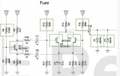
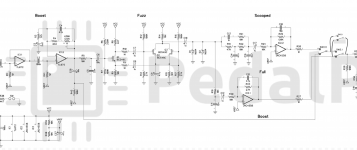
I think the modI would want to do is wire an additional toggle switch (SPDT) in parallel with the A1/2/3 one. Like this:
Screen Shot 2020-10-13 at 1.09.31 PM.png

When this switch is down and the 3-way is up, it would go through both the full and scooped circuit paths. I am assuming that when they are both down (or 3-way middle, SPDT top) it behaves identical as if the SPDT wasn't there...because basically the switches are to identical paths, it just creates two pathways with the same resistance and so the electrons flow just like they would.

I'm not sure what would happen if you had them both top...my guess is it would probably sound like mostly the boost as that would be the path with least resistance, but maybe some weird artifacts from the scooped fuzz circuit? I doubt it would mess anything up based on my (albeit minimal) knowledge of how circuits work.

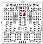
I'm assuming that A1/2/3 is one side of the DPDT's pins and B1/2/3 is the other. Not sure which is which (and if 1 is top or bottom of the pcb) but it should be easy to tell with the continuity mode on the multimeter and the schematic for the hole of the closest component and the switch pins.

I think this all makes sense, but just wanted to check to make sure I'm not missing something. I'll share whenever I get this going.
 
EDIT: Doh, nevermind, all I had to do is read your post a little better. ?

You should be able to add a SPDT toggle switch to connect these two points together to activate both Full and Scooped while in either Fuzz mode.
Boost mode would remain unaffected.

The Boost path is coming straight off of an opamp output so I suspect you are correct, it would swamp out the other two if activated with either (or both) Fuzz modes.

Board-RefDes.jpg
 
Last edited by a moderator:
Now we just need a little parallel blender to run both independently with their own volumes and we’ll be in business!

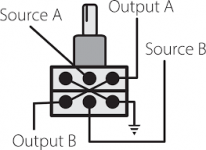
That's an interesting thought, I bet a blend knob for this one could be achieved experimenting with R26, R27...maybe a dual gang pot set up to be two variable resistors, where one's value increases while the other decreases.

Maybe this one https://www.taydaelectronics.com/1k-ohm-linear-dual-taper-potentiometer.html

you'd get 500 ohm for both values at 12 o'clock...so possibly do 500 ohm series resistors for each of these. but if the boost is going straight into the eq from the opamp (coupling cap aside), my guess is it probably would be fine at the lower resistance...maybe hit the EQ a little harder but I doubt it will really have much effect.

You should be able to add a SPDT toggle switch to connect these two points together to activate both Full and Scooped while in either Fuzz mode.
Boost mode would remain unaffected.

Ah yeah, so this would connect A1 and B3 in up and then I'd just wire up down to be off...that seems like a much smarter way to do it hah

---

I think I might also try some different NPNs in the fuzz section to see what I can get...and an 072 instead of the 4558 (though talking with a friend, that one will probably not make a difference)

Thank y'all! Excited to get to messing around with this one.
 
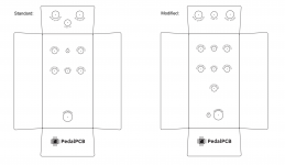
Been racking my brain trying to figure out if it's possible to fit all this stuff...do you think this is feasible?


Screen Shot 2020-10-14 at 10.45.55 AM.png

Modifications:
- Moving entire PCB up slightly
- Replacing LED area with toggle switch, the pins should be right above the top edge of the PCB I think
- Move LED down with footswitch (they might need to be spaced a bit more to fit the 3PDT footprint)
- Moving down DC jack and spacing out audio jacks very slightly (This is tight, I know...I might have to move the dc jack to the side of the pedal)
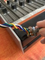
- Putting dual gang pot underneath bottom of PCB...using the wiring method as pictured below, the dual gang is maybe 2mm deeper than a dust-shielded standard pot. I think this will work with some electric tape on the bottom of the dual gang to make sure it doesn't come in contact with any of the pcb below?


IMG_4499.JPG
 
Not sure if it helps but The Dirty Sanchez pcb on the site has a drill template for 6 knobs and a toggle. The toggle is mounted on the side but I mounted it above the DC jack on the north side with all the in/outs.
IMG_20190624_182816.jpg
 
Last edited:
Not sure if it helps but The Dirty Sanchez pcb on the site has a drill template for 6 knobs and a toggle. The toggle is mounted on the side but I mounted it above the DC jack on the north side with all the in/outs.
View attachment 7007

this is helpful. Seeing this, I now know trying to space the top mounted jacks more than the drill template is a no-go. But it looks like there should be space for the top toggle and the dc jack without trouble. Good to know that you can stack the toggle/dc jack if it comes to that.
 
I’d probably side mount the extra pot too, I see that being a set and forget kind of thing...maybe even an internal trim set. Stoked to see how this progresses either way!
 
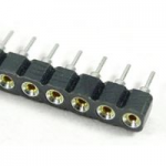
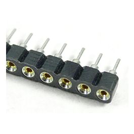
And by socket, I guess basically ripping apart one of these: https://www.mouser.com/ProductDetail/Mill-Max/110-44-308-41-001000?qs=YW4OkVwgsvJT3tgN9q9ibg==&gclid=EAIaIQobChMIhLW5vde07AIVVcDICh3Azw33EAQYAyABEgJj3fD_BwE

and soldering the little metal sockets into the pins and plugging my components into them.

Just get a couple strips of these and you can break off whatever length you want, it's what they're made for.
1602708910447.png
 
Sorry to bump an old thread but...

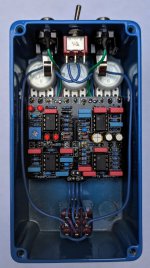
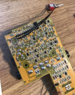
I recently bought the behringer superfuzz on a whim given the price, and it’s real cool, never thought I’d be interested in fuzzes. After reading this thread I tried wedging the switch between the two positions, kinda tricky to do but it’s a cool option. Since it takes a minute to get it right I just opened it up and tacked a switch on to the correct lugs:

18F45EAF-9420-4B45-84D4-C230A364470A.jpeg

works as expected but now I’m thinking, would a dual gang pot wired up like a usual blend knob work to blend the two together, say I want a little more fuzz 2 flavor?

something like this:

650D90C1-6349-41C5-917D-7BB205B8CC83.png

or is a different layout preferable in the middle of a pedal circuit? If this is fine what pot value should I get?

I plan to order the ‘hyped fuzz’ pcb but I’m in the U.K. and shipping/customs adds up quick so I usually try to order a few pcb’s at a time, still deciding what else I want.
 
Never mind answered my own question, I was about to box it up but decided to add a resistor in series with the switch. Tried 1k8 first, but that made the extra switch basically do nothing. Tried 320R and that gives a cool 60/40 blend of whatever fuzz setting I’m on.

when I eventually build the hyped fuzz pcb, I think jlmitch5dev has the right idea.

could probably do away with the switch entirely and just use a blend knob.
 
Back
Top