I/O and DC jack enclosure contact

brightlight

Active member
I have a very amateur question regarding something I recall reading in passing a while back concerning paint + rough edges inside of enclosures.

I recall reading that when you have for example a pre-drilled and powder coat painted enclosure from Tayda that the little bit of paint residue and rough inside edges can cause the I/O jacks, DC jack, and pots to have improper contact with the enclosure. I get it from a physical comfort stand point that those rough edges could make your jacks, etc not fit quite snug, but what is the logic behind these parts HAVING to make good physical contact with the enclosure?

I use those cheap commonly recommended plastic DC jacks from Tayda so I think i can rule out that this parts needs to make enclosure contact for grounding purposes, in fact I think you'd wanna avoid it since this seems to be a common issue for people using metal DC jacks.

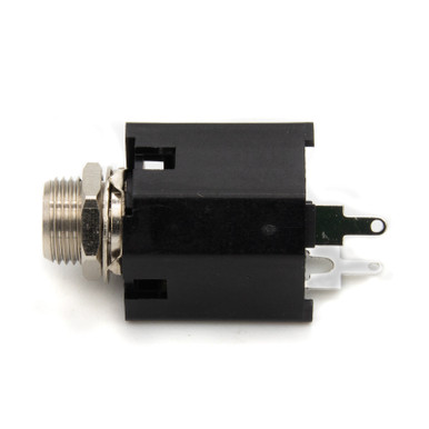
But for the I/O jacks do they need to make perfect contact with the enclosure for grounding purposes somehow? Obviously the hot tip shouldn't be touching anything except the wire hooked up to it, but does the sleeve rely on enclosure contact for grounding?

I've read the basic workflow thread about 10 times at this point and I notice paint on the inside of that example enclosure. Is the the actual drill hole that needs to be completely free of paint or that entire internal backside of the enclosure?

Also does any of this apply to pots or only the other external components?

Thanks for your patience, I hope I was clear enough with my questions!
 
You’re on the right track. The issue is solid electrical connection between the sleeve (of metal I/O jacks) and the enclosure to, among other reasons, mitigate RF interference by making the enclosure a shield. The DC jack should indeed be isolated. The metal housing of pots are not electrically connected to the lugs, but they should also have good contact.
 
To ensure I get a good jack ground connect to the enclosure, I add a 3/8" lock-washer between the jack and the inside of the enclosure. The teeth on the lock-washer dig into both the jack's metal shroud and the inner surface of the enclosure. Once tightened, the teeth can cut thru any paint on the inside - as long as the paint on the inside is not too thick.

In the attached image, you can see how the lock-washers fit nicely between the jack and inside of the enclosure on this 1590B top-mounted jacks assembly. I use genuine Lumberg DC and ¼" jacks. The DC jack should have no direct contact with the enclosure and the plastic housing assures that. I also use those plastic potentiometer dust-caps on any pots that hover over any portion the PCB's solder-side.

1590B_TopMount_Drill_Points_00.png
 
So I had another question regarding this. I think I recently came across @Robert saying in another thread that if you're connecting the PCB to both the input and output jack that grounding to the enclosure otherwise doesn't matter, the job is done. Is this true or did I misread something?
 
So I had another question regarding this. I think I recently came across @Robert saying in another thread that if you're connecting the PCB to both the input and output jack that grounding to the enclosure otherwise doesn't matter, the job is done. Is this true or did I misread something?
The circuit ground needs to have connection to the enclosure somehow. If at least one jack sleeve doesn’t have a solid connection to the enclosure, then all you’re doing by connecting both jack sleeve lugs to circuit ground is connecting the in and out cable grounds together.

If, for example, you have isolated jacks, you should connect both jack sleeve lugs to the circuit board grounds because they won’t have continuity through the enclosure. Since they’re isolated, though, you’ll need to make a ground connection some other way. Non-isolated jacks (e.g., regular metal sleeved ones) will have continuity between the sleeve connections if they make solid contact with the enclosure (i.e., there isn’t powder coating getting in the way).
Understood, thank you. So contact enclosure is required no matter what. This is just me trying to save a step, albeit a small one.
 
1 solid and reliable contact between the enclosure and ground is all that is required if you are establishing ground for everything by alternative methods(black wire).Don't loose sleep over every hole being cleaned. It's more about good electronics/electrical practices and ensuringing the enclosure can't be a conductor (of noise or electricity). Pedals aren't fully shielded anyway. We poke holes in them all over.
How many OEMs have made plastic pedals(looking at you soundtank) or pedals with plastic/rubber baseplates? Battery doors?
Ground all the things, but only once.

Furthermore, "best" practice is to isolate the jacks and have all grounded items share a single ground point of contact. This is called "star grounding" and is necessary in large audio systems(think studios and live audio) to avoid ground loops.
How much this matters in pedals and with this small of a potential loop is debatable. I feel that if this was necessary , a ground lift on output jacks would also be necessary. (Some isolate their output jacks as it should be grounded by the next circuit in line)
But if you want some toilet reading, googfu star grounding one day.

Hope that muddied it up for you good enough 😜
 
Understood, thank you. So contact enclosure is required no matter what. This is just me trying to save a step, albeit a small one.
If you wanna save that step buy the @StompBoxParts jacks with the teeth

 
Some pedals use a spring or something else conductive from the PCB to the enclosure when the build requires isolated jacks, EHX does it a fair bit:


SUPER EGO, copper tab at top of enclosure (sometimes you'll see tape over the enclosure side of the copper tab) :

electro-harmonix-superego-guts-3-jpg.604341


EHX Memory Boy, Spring Method (lower left corner of PCB near battery snap):

IMG_0766_crop.jpg

rs=w:1280


Ring & screw method of grounding board to enclosure:

13124-05-600x600.jpg


I've seen the wired-ring stuck under the screw of an enclosure lid instead of drilling another hole in the enclosure, too.
Wow that was very cool to see, thanks for putting this together!
 
Back
Top