You are using an out of date browser. It may not display this or other websites correctly.
You should upgrade or use an alternative browser.
You should upgrade or use an alternative browser.
Identify Nuetrik Jack
- Thread starter swelchy
- Start date
finebyfine
Well-known member
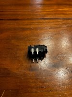
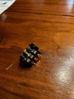
Got a picture? Is it offboard or on the PCB, and what type of switches are the additional 2 contacts?
PunchySunshine
Well-known member
RetiredUnit1
Well-known member
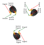
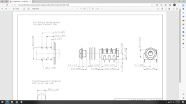
If you look at the top of the jack while plugging in a plug, you'll see the switch raise up and become disconnected. That's the switched side(edited I think the part that doesn't raise is the switch side). The front of the jack where the nut is, is the ground, the next two are the ring and tip with the tip being closest to the back. I always have to look at the diagram I made instead of rethinking it. I've never seen a five pin, are you sure the original wasn't snipped? Be sure to use wire cutters that are designed for thick copper and steel, don't use the ones just made for thin wire or they'll be AFU and how would I know that if I didn't ruin a pair doing just that? lol....


What is busted about the jack? Can you ohm it out still?
Can't think why a whammy would use switched jacks... I don't think any of them used batteries as the had AC supplies for v1-4 and ran 3.3v for the digital and 12v internally via one half wave and one full wave rectifier, again iirc.
Check the traces/ohm the pads and see if the pins connect via trace. Ohm each side of the jack and if ring and sleeve connect.
I'm betting that it's a modified stereo jack and only utilizes tip and sleeve, hence ring being cut on one side.
Or ring and sleeve short/connect on the pcb.
If that's the case, just use a stereo jack.
The only other thing I could think of is, if one side is switched, it's switching ground since they are AC input only(v1-4) so ground is established via the jacks, unless it's running on a crazy virtual ground network.
swelchy
Well-known member
dropped with instrument cable plugged in and messed it up and the cable doesnt engage tightly plus the threads are jacked upWhat is busted about the jack? Can you ohm it out still?
Can't think why a whammy would use switched jacks... I don't think any of them used batteries as the had AC supplies for v1-4 and ran 3.3v for the digital and 12v internally via one half wave and one full wave rectifier, again iirc.
Check the traces/ohm the pads and see if the pins connect via trace. Ohm each side of the jack and if ring and sleeve connect.
I'm betting that it's a modified stereo jack and only utilizes tip and sleeve, hence ring being cut on one side.
Or ring and sleeve short/connect on the pcb.
If that's the case, just use a stereo jack.
The only other thing I could think of is, if one side is switched, it's switching ground since they are AC input only(v1-4) so ground is established via the jacks, unless it's running on a crazy virtual ground network.
xefned
Well-known member
That missing pin (on a new 6-pin) would be disconnected when the instrument cable is plugged in.
If there are 6 holes on the PCB, you can use all 6 pins. If there are only 5, snip the missing one off, or bend it out of the way.
Similar threads
- Replies
- 2
- Views
- 104


