In This picture

djmiyta

Well-known member
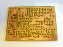
I want to etch this board but am unsure what the small solder pads that don't seem to connect to anything are for. Are they necessary? My guess was they are vias to connect one side of the board to the other but this is a single sided board so I don't know . Can anybody clue me in?
 

Attachments

  • Openhaus_PCB-01.jpg
    Openhaus_PCB-01.jpg
    227.7 KB · Views: 42
  • Like
Reactions: fig
Soooooo.....my assumption is correct? and I can ignore them on my etch? Mr. Fig kinda directed towards you since you're the only respondee so far (thats not a shot at or to anybody just to be clear) Thank you by the way
I have tried to build this one at least 3 times 3 different layouts and I have a gut feeling that I might not like its flavor but now it's a different matter Now it's personal. I only had 2 times I've had to re-etch a board due to something I messed up enough to warrant a whole new etch both times the 2nd etch worked fine and here I'm on a 4th one. No way I'm letting this effect win, if I can do Schumann and Lovetone pedals I can do this.
I WILL PREVAIL!
 
If it is a 1 layer board... I would not understand the need for vias... except to run jumpers, which I guess is not the case.
 
NICE! yep thats the one . What's your take on it? If you have one right now my pedal to beat is the Diezel VH4. Does it have more gain than that? My assumptions I'm taking for granted
If it is a 1 layer board... I would not understand the need for vias... except to run jumpers, which I guess is not the case.
That's how I'm seeing it. It's a lotta holes to drill so any less is better.
Alright then I'm off to make me an Openhaus. Thanks for the help forum members which I now will refer to as my ......friends.
 
  • Love
Reactions: Nic
Looks like it’s got traces on both sides then.
I don't believe so. I found another layout that matches the 1st pic I posted. So I got high hopes.
Just one thing I'm not so sure about is the square pads for the diodes if it's the cathode or anode going off Robert"s layouts it would be cathode I believe. Since I'm powering it from +18v I don't want to fry any of the chips
 

Attachments

  • 002- openhaus layout.pdf
    250.8 KB · Views: 6
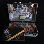
What a nimrod I am after looking at the newer pics I figured it out. They're not vias they're holes for the wire to pass thru.
just caught on as I was doing my transfer.Nice
 
Back
Top