

neiltheseal
Active member
Hello again, I'm back with another issue that I'm struggling with. Can anyone help please?
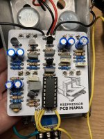
I recently built the Keepressor (Keely compressor from PCB Guitar Mania). (build docs https://pcbguitarmania.com/wp-content/uploads/2021/12/Keepressor-Building-Docs-1.pdf).
The pedal "works" but not like I had expected. I built a dyna comp which compresses like I expect it to. This Keepressor is very subtle
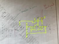
With an audio probe I have found something that might be an issue, although Im not sure what do do about this. The audio signal seems pretty strong up to the base of q3. When I touch many of the parts after this I get signal for an instant which disappears.
D3 - the signal is fine on the cathode.
D4 - signal for a moment on the cathode the disappears
Q3 - signal fine on the base, distorted and metallic signal on collector but consistent
Q5 - signal on base for a moment before disappearing, distorted and metallic, but consistent signal on collector
R20 - signal disappears after a moment
R21 - signal fine on one end (connected to pin 3 volume), but on the other side same problem as above.
C12 and C13 - Signal disappears
I have checked all of the parts (twice) and they are correct. Transistors and capacitors are oriented correctly.
I had the c5 issue mentioned in the build docs but have fixed this. Once fixed the pedal now works and definitely compresses. The issue is that it is really subtle and most knobs don't audibly do that much.
The pedal sounds ok, but it's a bit of a waste of a compressor at the moment as it is barely noticeable. Not like the dyna comp which is very in your face at high settings.
VOLUME: At full volume the pedal is about unity volume.
ATTACK: turned fully CCW has a mild overdrive sound, that I quite like. Compresses slightly more CCW.
SUSTAIN: seems to work like the sensitivity on a Dyna comp, although it only compresses about 1/4 of a Dyna comp
CLIP: I have no idea what clip does, except for a mild volume boost.
I recently built the Keepressor (Keely compressor from PCB Guitar Mania). (build docs https://pcbguitarmania.com/wp-content/uploads/2021/12/Keepressor-Building-Docs-1.pdf).
The pedal "works" but not like I had expected. I built a dyna comp which compresses like I expect it to. This Keepressor is very subtle
With an audio probe I have found something that might be an issue, although Im not sure what do do about this. The audio signal seems pretty strong up to the base of q3. When I touch many of the parts after this I get signal for an instant which disappears.
D3 - the signal is fine on the cathode.
D4 - signal for a moment on the cathode the disappears
Q3 - signal fine on the base, distorted and metallic signal on collector but consistent
Q5 - signal on base for a moment before disappearing, distorted and metallic, but consistent signal on collector
R20 - signal disappears after a moment
R21 - signal fine on one end (connected to pin 3 volume), but on the other side same problem as above.
C12 and C13 - Signal disappears
I have checked all of the parts (twice) and they are correct. Transistors and capacitors are oriented correctly.
I had the c5 issue mentioned in the build docs but have fixed this. Once fixed the pedal now works and definitely compresses. The issue is that it is really subtle and most knobs don't audibly do that much.
The pedal sounds ok, but it's a bit of a waste of a compressor at the moment as it is barely noticeable. Not like the dyna comp which is very in your face at high settings.
VOLUME: At full volume the pedal is about unity volume.
ATTACK: turned fully CCW has a mild overdrive sound, that I quite like. Compresses slightly more CCW.
SUSTAIN: seems to work like the sensitivity on a Dyna comp, although it only compresses about 1/4 of a Dyna comp
CLIP: I have no idea what clip does, except for a mild volume boost.
") Nice project, by the way!
Nice project, by the way!