King Nothing No Effect Signal

joelorigo

Well-known member
Hello all, I am getting bypass signal, but nothing when activated, including no LED. I saw a previous thread with the same problem so I have already followed some of the advice there. One thing to note is that I socketed C3 & C4 to experiment later with the bass response that was discussed in an earlier thread.

First, these continuity tests are all good. (I should note that the LED comes on D&E, normal?)
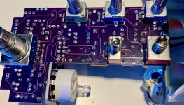
3PDT switch pins:
Pedal bypassed:

  • 1 -> 2
  • 4 -> 5
  • 7 -> 8
Pedal active:
  • 3 -> 2
  • 6 -> 5
  • 9 -> 8
Looking at the top row where it connects to the main PCB:
Pedal bypassed:

  • A -> F
  • B -> C
  • No continuity on other top pins
Pedal active:
  • A -> B
  • C -> D
  • E -> F
Pins C is ground and D is the LED cathode connection, and they correspond to switch pins 5 and 6 respectively.
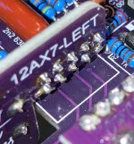
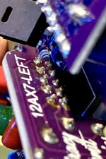
Pin A is the input jack and F is the output jack. Pin B is the effect input.


Then, these voltage tests (using a 1.7A Godlyke Powerall 9v adaptor):
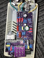
V+ pad, should be close to 9VDC (typically lower due to diode drop, but will depend on your power supply) - I get 9.17

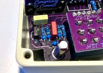
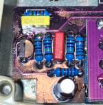
cathode pad of D2. This is the high voltage rail, it should be 230VDC or so - I get 0, so obviously a problem there!

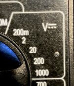
I am including a photo of the section of the DMM to make sure I was using the correct section.

Oh, actually the first thing I tried was a different tube.
 

Attachments

  • IMG_7817.JPG
    IMG_7817.JPG
    1.1 MB · Views: 31
  • IMG_7816.jpg
    IMG_7816.jpg
    744.6 KB · Views: 31
Last edited:
When your talking High Voltage, Members are weary like myself to offer assistance.
Definitely one for Vigilante398 to look at!
Could be the 555 timer via the IRF740 if your not getting 230VDC at the cathode pad of D2!???
 
First things first, verify component values, particularly around the SMPS. Verify you have a UF4007 and not a 1N4007, as a standard rectifier will not work, you need an ultra-fast rectifier. If you're getting 0V on the HV rail, that's obviously the reason the tube isn't passing signal, you just need to figure out why the SMPS is unhappy. Another thing to do is verify that the NE555 is fully inserted into the socket, as improper seating in the socket is a common cause of SMPS issues.
 
First things first, verify component values, particularly around the SMPS. Verify you have a UF4007 and not a 1N4007, as a standard rectifier will not work, you need an ultra-fast rectifier. If you're getting 0V on the HV rail, that's obviously the reason the tube isn't passing signal, you just need to figure out why the SMPS is unhappy. Another thing to do is verify that the NE555 is fully inserted into the socket, as improper seating in the socket is a common cause of SMPS issues.
Good point on the UF4007, I ordered what was on the BOM or I would have used a 1N4007 being the same numbers!???
 
When your talking High Voltage, Members are weary like myself to offer assistance.
Ahhhh, that makes sense. This is my 4th high voltage tube build, the first 3 worked with out any issues so troubleshooting this is a new, cautious area for me. In the other thread I mentioned, @vigilante398 also included this, which I followed very carefully when measuring the voltage:

WHEN CHECKING VOLTAGES IN HIGH-VOLTAGE CIRCUITS EXTRA CARE IS REQUIRED. IT IS RECOMMENDED THAT YOU ONLY HAVE ONE HAND NEAR THE CIRCUIT AT A TIME AND THAT YOU KEEP THE OTHER HAND BEHIND YOUR BACK OR OTHERWISE AWAY FROM THE CIRCUIT.
 
First things first, verify component values, particularly around the SMPS. Verify you have a UF4007 and not a 1N4007, as a standard rectifier will not work, you need an ultra-fast rectifier. If you're getting 0V on the HV rail, that's obviously the reason the tube isn't passing signal, you just need to figure out why the SMPS is unhappy. Another thing to do is verify that the NE555 is fully inserted into the socket, as improper seating in the socket is a common cause of SMPS issues.
I will check the D2 first. I DID get 2 UF4007 and 2 1N4007 diodes in the same Tayda order for several builds, maybe I got confused and put the 1N4007 ones in the King Nothing and Lab Rat boxes when sorting. If not, I will check the NE555 insertion and double check the rest of the components values.
 
I am 99.9% sure it is a UF4007. I cant visually prove it the way it is soldered to the board but the 2 1N4007 diodes I also bought are still in the little pink plastic bag, and the other one of the UF4007 ones I got is soldered to my Lab Rat PCB, with the "U" clearly visible.

I have used the photo of the PCB on the Conspiracy to Commit site to verify that I have all the correct values of all the other parts.

The NE555 - and the C3 & C4 caps - appear to be fully inserted in the sockets.
I also confirmed that your resistor values looked good while troubleshooting at the start of this thread.
Have you had a good look at the Solder side of the PCB for a bad joint or bridge, pay attention to the right angle header pins also!
 
I also confirmed that your resistor values looked good while troubleshooting at the start of this thread.
Have you had a good look at the Solder side of the PCB for a bad joint or bridge, pay attention to the right angle header pins also!
Thank you. I did look to see for any wonky soldering when I finished the PCB, before I started on wiring / assembly. I will double check that. Last year I had a problematic build and checked the soldering, and after days and days and pages and pages of you helping me troubleshoot - it was a solder bridge I missed!!!
 
I am not seeing anything too bad looking at the solder side. Anyone see anything?? I'll be happy to take some photos if anyone wants better/alternate views.
 

Attachments

  • IMG_7826.jpg
    IMG_7826.jpg
    405.9 KB · Views: 10
  • IMG_7825.jpg
    IMG_7825.jpg
    383.4 KB · Views: 10
  • IMG_7824.jpg
    IMG_7824.jpg
    439 KB · Views: 10
Here are a few. Q1 is a J201 that ti got from either GuitarPCB or Stompbox Parts.
 

Attachments

  • IMG_7830.jpg
    IMG_7830.jpg
    620.7 KB · Views: 9
  • IMG_7828.jpg
    IMG_7828.jpg
    820.4 KB · Views: 8
  • IMG_7831.jpg
    IMG_7831.jpg
    860.7 KB · Views: 9
  • IMG_7829.jpg
    IMG_7829.jpg
    794.7 KB · Views: 9
This is not the first time I have questioned the J201 BA17 in this picture as others have also???
Note the F in Fairchild!

This lot from Amazon don't even have an ''F''
1714435056078.png
 
Last edited:
Interesting. This is what I measured with the TC1 before I soldered.

Idss=0.36m, Id=0.22mA,@Vg=150mV, ID=0.00MA, Id=644mV

I have 6 more that look exactly like the one I used.

But this wouldn't cause the problem I'm having though, right? It means it might not sound like it should with a proper J201, right?
 
Yes, yes and no. I am 99% sure it is a UF4007. I would have to remove it from the PCB. Which I can do.

EDIT: this is what the TC1 measured the UF4007 before soldering if that helps confirm it:
Ir=4nA, Uf=600mV

One other thought I had, after I was done populating the PCB, I used alcohol and a toothbrush to clean the bottom, if some of it got inside the 100uH inductor, would that cause a failure??
 
Last edited:
Yes, yes and no. I am 99% sure it is a UF4007. I would have to remove it from the PCB. Which I can do.

EDIT: this is what the TC1 measured the UF4007 before soldering if that helps confirm it:
Ir=4nA, Uf=600mV

One other thought I had, after I was done populating the PCB, I used alcohol and a toothbrush to clean the bottom, if some of it got inside the 100uH inductor, would that cause a failure??
That's a good question. I'm not sure what their coating is made of and if it could be bothered by isopropyl. I would be a little surprised if that was it as I would hope most electronic components to be able to withstand typical flux removers which are often more aggressive than isopropyl, but stranger things have happened. Could be worth trying a new inductor if you have a spare on hand, should be a fairly easy swap to try out.
 
I replaced the inductor, and swapped out the NE555 while I was at it. Still the same issue. I then removed the IRF740 (of which I broke off the thin part of the middle leg!) to make space so I could remove D2 to confirm that it is a UF4007. It is.
 
Back
Top