Tyrian - clean signal, no distortion/effect

xxvga

Member
Hi all, I'm a newb here.
I am on my third pedal, the Tyrian.
My first was the Sabbath. it doesn't work but I chalk that up to what is probably sloppy soldering. I ordered a new pcb and will try again.

Second pedal was the face melter. works great, although some funnny clipping when the 'Dirty' is turned all the way up. but overall awesome.

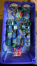
so now my Tyrian. I worked slow and I worked clean. to me it looks great.
bypassed signal good (a little noisy) but it's otherwise clear and good.
when switched on the LED fires up, volume/signal seems to drop a bit and stays clean.
I did an audio trace and of course i seem to be able to trace audio through the entire pedal...no surprise considering i'm still getting a clean signal when the pedal is engaged. it's just not kicking in the distortion.
on the audio trace i didn't hear a sound when testing the wiper lug of the A50k volume pot. thought it was faulty so i switched out for another pot but same thing. i measured the pot and it reads 50k as it should

any thoughts? I've searched in the forums but just don't seem to find anything that helps.
i've tried switching out the foot switch as well. the footswitch looks like a sloppy job but i have looked very closely and solders are solid and nothing is touching anything it shouldnt be

any ideas?


Thanks in advance
Mike


sorry for the gigantic picture :)
IMG_9940.jpg
 

Attachments

  • IMG_9940.jpg
    IMG_9940.jpg
    471.4 KB · Views: 6
I think the problem is on the input output jacks. Assuming the black wire goes to the ground for the input, output and power. I believe you can cut the yellow and green wires and run the blue wires like this. 1711680779167.jpeg
 
Yes thank you. You are correct. I mentioned that in the picture the jacks were wired incorrectly but that was fixed before I did all my testing. Anything else you can think of?
 
Thanks so much for your help. I did clean up that piece but it wasn’t the issue. The bypassed isn’t super noisy but the level drops when switch on and no effect I have swapped the switch as well I know the wiring on the switch is ugly but I think it’s clean nothing touching that shouldn’t be I think 🤔 IMG_9952.jpeg
 
It looks like maybe you forgot to solder your IC socket, there--the IC closest to the bottom left where "Tyrian Distortion" is printed.

Also, a component leg directly east of that IC's pin 2 (pin below the square one).

Solder joints all look a little low/could benefit from a reflow. They should look like shiny and tidy tiny Mount Fujis, not flat, not blobby, not other shapes.
 
yup i know that IC wasn't soldered in when I took that particular pic. was waiting on new sockets from Tayda which arrived and it was all installed before I did my final tests. good eye.
I'll go back and try to make some mount fujis and see if that helps.

when i use an audio probe i'm getting audio through the circuit but it should be distorted correct? I'm just using a tone generator app. but it shouldn't come out clean sounding. so the signal gets all the way through, just the distortion isn't triggering.
very weird. but i wont give up :)
 
Try wiring it like this. Also I would clean the bottom of the board with isopropyl alcohol and a toothbrush. View attachment 71877
thank you. i did mentioned that this picture showed the jacks were wired incorrectly but that was fixed before I did any of my testing. I also showed the other side of the circuit which I had washed with alcohol as well. now i'm trying to make sure all the solder points are good.
 
thank you. i did mentioned that this picture showed the jacks were wired incorrectly but that was fixed before I did any of my testing. I also showed the other side of the circuit which I had washed with alcohol as well. now i'm trying to make sure all the solder points are good.
I thought that pic was new as the material I recommended removing from the foot switch was taken out. I think it’s possible the tip and ring are switched somewhere. Often it will still pass signal that way but is noisy as your signal is now on the outside of the shielding.
 
Ok so I IMG_9958.jpeg resoldered whatever I could and I have completely replaced the switch. Still have the same issue but something new happened. When the effect is on one of the leds on the board goes on. This didn’t happen before and now it’s only one. At least something changed. A new clue right? Lol
 
1711847684969.jpeg
I’m still fairly certain that this wire should be what are now green wires. These are the same jacks I use on my pedals.

1711848264176.jpeg
I have marked on this connector where I think they should go. From the side you can see the green connects to the little bent piece which will contact the tip and the yellow contacts the barrel which will contact the shielding on the cable. On the top of the board the 3 wires not marked + are ground and should go to the terminals I have marked yellow or the center pin of your DC cable if using a boss style center negative DC cable. The wires coming off the foot switch are your positive signal and get wired to the green connectors. When you are in bypass mode it works but is noisy is your signal is getting send down the shielding of your cable. When you engage the pedal you are putting voltage into the equation and it is going to ground.

I apologize if I am being redundant in my responses and will not suggest this to you again but I’m fairly certain this is if not the issue one of them.
 
I really appreciate you trying to help so if you’re being redundant it’s only because I need you to be :)
So here are a couple other pics. I’m pretty sure I have the right wires to the sleeve and tip. Maybe I’m just not understanding something. Sorry it’s all a bit new to me.

Does this look ok?
IMG_9969.jpeg IMG_9968.jpeg
 
Totally get and it and appreciate your help. So the top of the pcb goes to the negative and the switch goes to the tip? I thought it was the other way around. I’ll try it.
 
The pads I have circled in black are all ground you can even use one wire and run it to both jacks and the DC power plug if you want. The pads in green go to the foot switch and are the ins and outs for the board.
1711853818797.jpeg

On the foot switch in the picture 1711854048530.jpeg
it makes the green connections I drew in one position and the blue in the other. When it makes the green connections it takes the signal in from the left across the blue wire and out on the green wire on the left. The middle connection sends the input from the Pcb to the ground in the center to reduce noise. When it makes the blue connections the signal comes in on the green wire to the left through the yellow wire to the board input then out the short green wire and to the output. The black and white wires connect on the middle to light up the indicator LED.

Also the black and white wires to the foot switch should be swapped.
 
  • Like
Reactions: Nic
Back
Top