orangetones
Member
Hello!
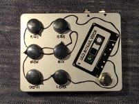
Thought I would share my artwork and issues in setting up this pedal. I'll say that the one issue I had was with the input FET. I used a J201 through hole, as I have a bunch of the from years ago. My advice would be to watch the pinout. It works be nice if the build document was compete and labeled the D S and G on the board to easily help people who are using different components. I had to investigate the through hole layout and then twist around the legs of the J201. Works perfectly.

Thought I would share my artwork and issues in setting up this pedal. I'll say that the one issue I had was with the input FET. I used a J201 through hole, as I have a bunch of the from years ago. My advice would be to watch the pinout. It works be nice if the build document was compete and labeled the D S and G on the board to easily help people who are using different components. I had to investigate the through hole layout and then twist around the legs of the J201. Works perfectly.

