ItsASecret
New member
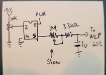
I built the Low Tide Modulator, what a rad pedal! Now that I've built it I'm trying to work through parts of the circuit to better understand it. Here's my crappy drawing of the randomizer circuit:

Here's what I think is happening:
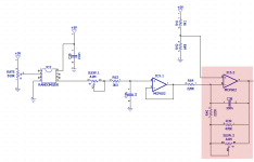
The Attiny13A (the Randomizer) looks to just have a single input on pin 2 (The wiper output from the 10K pot voltage divider connected to the +5V rail) and an output on pin 5 that connects to one side of the dual gang slew pot. My guess is that the output is just a PWM signal whose value changes to a random value between 0 and 5V. Rate at which that value changes is set by the input at pin 2. The output is connected to one side of the slew pot (which is wired as a variable resistor) then through a 3.3k resistor and to the non-inverting input of the MCP602. A 1uF capactior (cap C36) is set across that MCP602 input and ground.
As the voltage at pin 5 changes , cap C36 resists that change, so you get a slow 'slew' as it adjusts to the new voltage level set at pin 5. The slew pot effectively changes the current being fed to the cap (with the 3.3k acting to limit the maximum current if the slew pot is set to zero ohms). Higher current means a faster slew rate, lower current means a slower slew rate.
Does this make sense? Can't 100% verify as my oscilloscope is buried in my baby's closet. Might be cool to try and modify the attiny to have different patterns if this is indeed what's going on.


