You are using an out of date browser. It may not display this or other websites correctly.
You should upgrade or use an alternative browser.
You should upgrade or use an alternative browser.
M800 PAL 800 JCM Emulator run at 18V?
- Thread starter cooder
- Start date
MightySmallElectrons
Active member
Looks like the J201’s will run fine. I’m guessing that as long as your electrolytic is rated for over 25v you would be good.
But I wouldn’t trust my judgement and I’m curious to hear from someone who knows what they’re talking about.
But I wouldn’t trust my judgement and I’m curious to hear from someone who knows what they’re talking about.
Nostradoomus
Well-known member
Should be fine, might need to tweak the trimmers so they’re at 9v-ish.
Chuck D. Bones
Circuit Wizard
Actually, the topology is different. The Okko Diablo does not have trimmers because the drain voltage is set by the upper JFET. The trimmer setting in the M800 will have to be a compromise between 9V and 18V operation. Not necessarily a bad thing because you probably want it to sound different at 9V vs. 18V. Just trim by ear at both voltages. BTW, 1/2 Vcc is not a magic number, it's just a starting point in all of the JFET pedals.
Last edited:
cooder
Well-known member
Yeah cheers I noticed the absence of trimmers on Okko Diablo. Thanks for explaining!Actually, the topology is different. The Okko Diablo does not have trimmers because the drain voltage is set by the upper JFET. The trimmer setting in the M800 will have to be a compromise between 9V and 18V operation. Not necessarily a bad thing because you probably want it to sound different at 9V vs. 18V. Just trim by ear at both voltages. BTW, 1/2 Vcc is not a magic number, it's just a starting point in all of the JFET pedals.
I just tried it on my Build & it sounds Huge @18v, I found it more controllable at 9v meaning at so called ''Bedroom'' levels!
My trimmers are all set at 4.5v @ 9v Power supply.
Yes it works but you need to tame that Volume knob @ 18v's !
I always use 35v or higher on my Builds.
People looking for that ''Marshall'' sound should seriously look at building this pedal
It has gone a little ''Under the Radar'' as it is built in Small Quantity's.
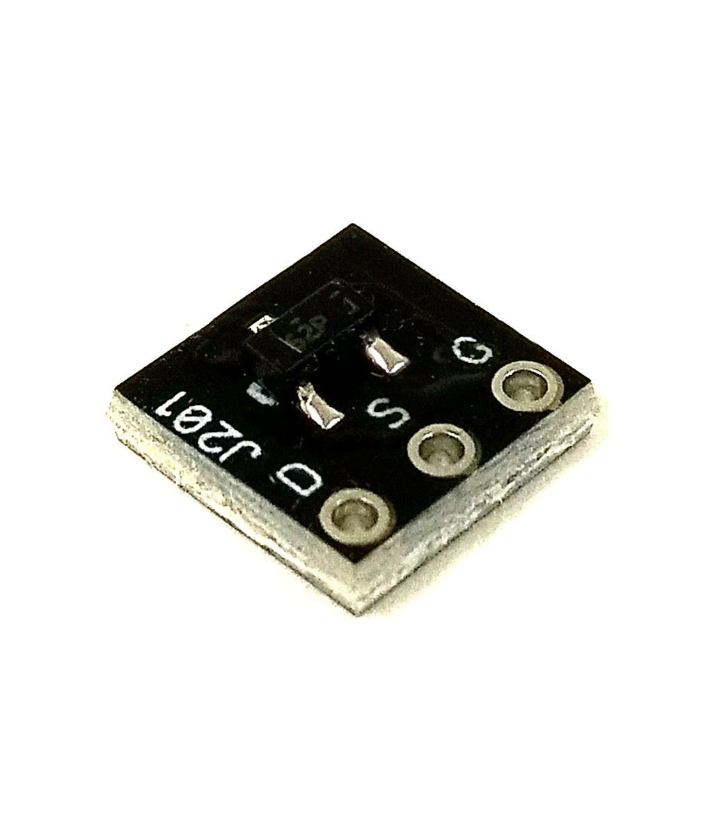
Purchase the PedalPCB Adaptor Board & save yourself some heartache with Fake J201's:
My trimmers are all set at 4.5v @ 9v Power supply.
Yes it works but you need to tame that Volume knob @ 18v's !
I always use 35v or higher on my Builds.
People looking for that ''Marshall'' sound should seriously look at building this pedal
It has gone a little ''Under the Radar'' as it is built in Small Quantity's.
Purchase the PedalPCB Adaptor Board & save yourself some heartache with Fake J201's:
cooder
Well-known member
Awesome, thanks for that!I just tried it on my Build & it sounds Huge @18v, I found it more controllable at 9v meaning at so called ''Bedroom'' levels!
My trimmers are all set at 4.5v @ 9v Power supply.
Yes it works but you need to tame that Volume knob @ 18v's !
I always use 35v or higher on my Builds.
People looking for that ''Marshall'' sound should seriously look at building this pedal
It has gone a little ''Under the Radar'' as it is built in Small Quantity's.
Purchase the PedalPCB Adaptor Board & save yourself some heartache with Fake J201's:
What do you mean by "I always use 35v or higher on my Builds."?
Would you run this from an even higher voltage supply to do that?
Moltenmetalburn
Member
I have run mine at 33-36V with an external charge pump. Sounds ok. Muxh louder. Caps are all 50V or higher. I previously tweaked trimmers by ear from the 4.5/half supply starting point at 9V.
hmm had another look at this. Been tweaking for a while at different voltages.
Even at 18V not all the the trimmers can limit the voltage enough to reach the halfway bias point.
seems like a bad idea unless the trimmer values can simply be adjusted higher to compensate.
Hopefully others will chime in again. Definitely takes more than just higher voltage caps.
Last edited:
Elijah-Baley
Active member
Hello.
I still never built none JFET emulator amp, but I guess I read about the Dr. Boogie that at higher voltage like 36v can help bigger trimmer value: 250k, 500k maybe?
I still never built none JFET emulator amp, but I guess I read about the Dr. Boogie that at higher voltage like 36v can help bigger trimmer value: 250k, 500k maybe?
Moltenmetalburn
Member
That is what I am hoping that a larger trimmer value is all that is needed.Hello.
I still never built none JFET emulator amp, but I guess I read about the Dr. Boogie that at higher voltage like 36v can help bigger trimmer value: 250k, 500k maybe?
The misbias at 18- 36 did sound a bit worse than 9.
Chuck D. Bones
Circuit Wizard
I would expect that higher voltage operation would require proportionately larger trimmers to find the sweet spot.
cooder
Well-known member
And how about we crank up the voltage to 250 V and make it the real tube amp....? LOL...")
Interesting discussion though. I wonder if at some point of increasing voltage it is a matter of diminishing returns, aka not hearing much difference...
And I'd love to see more schematics of circuits available here as I'm on a binge trying to learn and see what's happening on circuits.
For example how the 9 to 27 V switch is implemented on Duocast.
Paging Dr. BuGG...
Chuck D. Bones
Circuit Wizard
For example how the 9 to 27 V switch is implemented on Duocast.
When you see it, you will shit bricks.
Deceptively simple. All you need is an SPST switch between +9V and pins 1 & 8 of the charge pump. Disconect the charge pump and the 9V flows straight thru the diodes with no boost.
Alternatively, you can put an SPDT switch between the power rail and the charge pump to select either +9V or +27V. But why leave the charge pump running when it's not being used?
dankmetalsounds
New member
Newbie question - Instead of using a change pump, could you run 18v directly into the pedal to get the desired effect?
Chuck D. Bones
Circuit Wizard
Yes, absolutely. All the aforementioned caveats apply...
Similar threads
- Replies
- 21
- Views
- 2K
- Replies
- 4
- Views
- 1K
- Replies
- 69
- Views
- 29K
- Replies
- 4
- Views
- 1K