SOLVED M800 Transistor biasing

TravisM

Active member
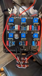
I just finished my first pedal, and everything seems to be working and sounding pretty good. I have lots of gain and volume on tap and the tone stack seems to work as expected as well. I don't have a baseline to judge this specific pedal however.

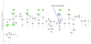
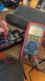
When I was biasing the transistors, Q5 would only vary between 9.48 and 9.02 VDC at max turns of trim pot 5. I expected that out of Q4, which is connected to the trim pot labeled tone. I validated VCC and ground at each point in the schematic. I also measured each component that I could with a multimeter before installation so I know the trim pot was within spec. I didn't check the JFETs that I bought, but they are the pre-soldered MMBFJ201 JFETs from the store here.

So my questions:
1) Is that an expected result for Q5?
2) Should I care if the pedal is working?

Thanks,
Travis
 

Attachments

  • M800_Circuit.JPG
    M800_Circuit.JPG
    127.9 KB · Views: 19
Check the values of the bias trimmer with your dmm. Is the trimmer relatively close to 100k? Tolerance is pretty high so if you're closer to 80k that's fine. I just want to check that your trimmer is working and close to the correct value.
 
Something is definitely wrong if you can't get Q5-D down to 5V. Hard to believe the pedal is working, so I gotta wonder
a) maybe there's a mistake in your measurement
b) there is other stuff wrong

You should be able to dial the drain voltage on every JFET except Q4 down below 6V.

How about some pix?
 
The reading is correct. I can turn the bias pot with audio going through the pedal and hear it changing the sound from off through very quiet to on. I tried using a braid to de-solder the trimmer but I'm afraid I can't get enough heat into it without damaging it.
 

Attachments

  • PXL_20211220_140710796.jpg
    PXL_20211220_140710796.jpg
    665.1 KB · Views: 32
  • PXL_20211220_140740610.jpg
    PXL_20211220_140740610.jpg
    574.9 KB · Views: 27
Thanks, I concur. I doublechecked the order sheet from mouser and it seems I didn't even order a 470 Ohm resistor. Somehow I managed to mess that one up multiple times then. Once when I ordered, and once again when I laid out the components on the build sheet printout.
 
Success! There is still a Radio Shack in town that has components, so I was able to get the correct resistor. After much consternation removing the wrong-valued R11, the new one is in place and the pedal went from a mild-mannered overdrive to a fire breathing monster!
 
Damn Chuck D. Bones that's some set of eyes you got there:whistle: . I'm sure there's a trouble-shooting record broke somewhere.
And like you've said before it's all about that visual inspection and you gotta be thorough
I'd always get a chuckle when I go on a troubleshoot quest you come across a forum where somebody is saying their build doesn't work it must be the schematics or the layout and the thing is it's a documented verified layout and MUST be the scheme or layout that's wrong.
 
Last edited:
The vast majority of the time, the problem is workmanship. Many people have a hard time considering the possibility that they might have screwed up. We've witnessed time and again where some poor sod is blindly swapping out parts because they want the root cause to be a bad part.
it is always easier to try to swap out a socketed part before undertaking the effort to really troubleshoot a build....
 
Granted troubleshooting builds mmmm character but really I’d rather be listening to my new toy
So
My New Years resolution is to slow down when I do all my new builds for 2022. He’ll yeah I’m already happy for next year
That’s cause I still have e few to blow out this year
 
Back
Top