No power - desolate fuzz

diesin1stact

New member
Hello, everyone. I've successfully built 5 or 6 pedals so far but have run into a power problem that I can't diagnose.

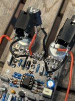
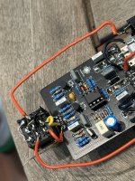
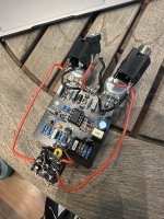
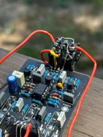
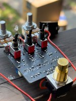
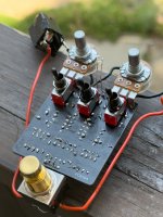
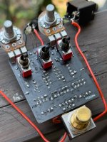
This is the Desolate Fuzz. I've swapped out DC jacks, reflowed some solder points that were a little dull and reversed the 2N3904 that is upside down in the photos. Any other ideas to try?

Haven't broken out the multimeter yet but when the pedal is plugged in, I'm getting nothing from the LED and no instrument signal through the pedal.
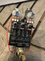
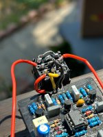
IMG_2475.JPG IMG_2474.JPG IMG_2473.JPG IMG_2472.JPG
 
I would really like to see the flux cleaned and all the joints reflowed… with no led it’s not a power issue yet since the switch is involved in the powering of the led and the wiring is a little melted… Are you sure you’re using a negative center plug and it’s wired correctly?
 
If you are getting no bypass signal then the footswitch and/or wiring is suspect. You should have bypass signal even when there's no power applied to the pedal.
Could just be the pix playing tricks on my eyes, but lug 6 of your footswitch looks like it’s come loose and twisted a bit. How much heat ya using there? And how long ya dwelling on them thar lugs?
 
Hello again, guys and gals. Thanks for all the advice. I cleaned off the flux to double check that there were no unintentional connections. That wasn't the issue so I went ahead and reflowed each and every joint before cleaning the flux away again. Still no love so I'm posting a fresh batch of photos for the brain trust here.

I checked all the pins on the foot switch and they're solid. A couple may have gotten a little bent when I was crimping wires for a mechanical connection before soldering but they're still attached and not loose at all.

I've never had an issue with pedals firing right up once I get them wired but now I'm having this issue with the Desolate Fuzz and also the B-Side Fuzz. The only thing I've changed is the solder I'm using. I'm now using Kester 44 (rosin core 63/37) instead of the ridiculously expensive WBT silver solder. I'm soldering at 670 degrees F but the joints look a little dull. It could just be that the WBT was especially shiny because of the silver content and lack of a flux core. But could my soldering temp have something to do with this? I'm feeling pretty strongly that something is up in my soldering but I'm at a loss as to what it could be.

I have the multimeter broken out and ready to measure whatever you guys tell me to measure.
IMG_2500.JPG IMG_2499.JPG IMG_2492.JPG IMG_2491.JPG IMG_2490.JPG
 
I don’t think I’ve seen anyone bend switch lugs like you’ve got your toggles there. I don’t think I’d trust them to take that. Could be a potential failure point. You could start by verifying that you’ve got continuity from the middle lug that switches to the outer lugs then same on the foot switch to verify that bent lug is also happy.

I doubt your solder brand is the problem.

I agree
 
Once when I was a kid I saw someone tying their shoes and I went, huh, so that's how you're supposed to do that. Learning by failure is my whole game! This is the first time I've tried it but I bent the switch lugs like I would component leads to keep them in place while I turned the board. If you guys think it's weird, it's probably weird.

I'll replace the toggles and the foot switch and see if that fixes it. I put in a new component at Q3 when i flipped it just in case it was damaged. Does anyone have a good resource for how to use a multimeter to diagnose a problem pedal?

Thanks again to everyone.
 
Desoldering and replacing toggles without damaging the board is a tough job (tougher with the lugs bent probably). I’d definitely test them first. They might be fine.

You should get continuity between the center lug and the upper lug in one switch position, center to lower in the other.

The foot switch is the same, there are just three sets of contacts.

YouTube is a great resource - try searching “multimeter tutorial”.

I’d also maybe search the model number of your meter and “pdf” if you don’t have a copy of the manual.

These Colin’s lab videos are pretty good:

 
is the first time I've tried it but I bent the switch lugs like I would component leads to keep them in place while I turned the board. If you guys think it's weird, it's probably weird.
Knowing how things fail is important. That said, don’t bend the lugs 😁

You need those lugs to stay right where the factory put them. Otherwise, you risk all sorts of mischief with your build.
 
There are some good Pedal diagnosis videos on Youtube. These can also help familiarize you with the processes others use to find the where there are issues.
Pedal Fault Diagnosis Search

If I'm having issues with a circuit I will often times audio probe the circuit if I am getting partial output of the effect. This can help identify bad or wrong value components, or maybe an accidental grounding of the signal.

If nothing works, I print out a schematic and then start testing continuity between each component and all the respective components which are connected on the schematic. This doesn't test any of the components, but it will tell you if you have a broken trace. I bought a non-working Procrastinator off Reverb last year and it ended up having a trace which had been burned when the person was assembling it. I had to add a jumper wire to the leg of another component to fix but that's all that happened to be wrong with that pedal.

Buying broke pedals to trace and fix has been a great learning experience for hands on work.
 
Back
Top