only 4 modes

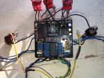
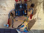
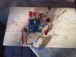
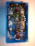
hello i assembled and soldered a arachnid its the second one
the first is working perfectly but the second has some trouble
actually, there is only the 4 first modes who are working

the 5. 6 .7 .8 mode/presets are the same that the 1 ; 2 ;3 ; 4

Is there some o,ne who figured the same problem out .
i verified all my weldings
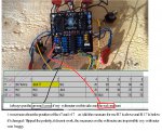
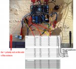
i mesured the voltage on the FV1 pin16 pin 17 pin 18 and this is the result on the attach files

please if someone have a soluion because i think once again i have to buy another arachnid pcb with the fv1 chip

thank you by advance
regards
 

Attachments

  • fv1 voltage.jpg
    fv1 voltage.jpg
    89.8 KB · Views: 10
yeah i tried this tip and on the first arachnid i soldered, it works perfectly

this is not a EEPROM problem because i also have the module8 eeprom and it works on the module8/arachnid pcb that i first bought and assembled
3 months ago
 
Are you measuring those voltages directly on the pins, or on the pads?

Do you think you could reflow the solder onto the S0 / S1 / S2 FV-1 pins?

BTW just for reference your pinout is backwards on your list, S0 : Pin 16, S1: Pin 17, S2: Pin 18.
 
hello okay i will try to reflow the 3 pins but im not sure about the result !!
and thanx for the informations about my wrong reading of the pinout
i will tell you if it's would change something

for the measures, i put the ground of my multimeter to the dc socket ground and with a voltmeter i checked all the volt directly on the FV1 S0, S1, S2 pins
I m from Marseille in France and my english is not too rich i can undertand all that you wrote but i have not got all the professionnal vocabulary especially in electronic

regards
 
okay i reflowed the pin 16 17 and 18 and this is nothing which changes
as previous, i ve only got 4 modes ... the 1, 2,3 ,4 then once again, the 1, 2 , 3 , 4
i tried a lots of things, remplace the TL074 the L78L33, switching the EEPROM
do you think that some capacitors could be disfonctionnal or another components ? Has it happened to you or someone you know
please tell me something to do or to test to make my pedal arachnid with 8 mode as i expected for the price i paid because i begin to think that it could be a technical problem with the FV1 or the PCB...as i told you i bought you the same pcb 2 or 3 mouths earlier and it 's working perfectly
regards
 
The pin 16, 17 & 18 voltages look strange. They should all be the same voltage when they are high. Check R7, R16 & R17, make sure they are all 100K and not something else. You could also measure the voltage on pin 3 of any of the CTRL pots. It should be 3.3V for every position the rotary switch.

There is no way that the TL074 would cause this.
 
of course and i also uploaded a video on youtube


the last one (the pcb on the enclosure - img_20191022_151212) was the first arachnid i soldered on october and it works perfectly - all the mode are available
i must have done some exchanges of some components between the blue good one and the nonworking arachnid to test some options and i could not find the problem

i have done all that i can do according to my electronic knowledge
 

Attachments

  • IMG_20191228_135038.jpg
    IMG_20191228_135038.jpg
    548 KB · Views: 8
  • IMG_20191228_135151.jpg
    IMG_20191228_135151.jpg
    998.4 KB · Views: 8
  • IMG_20191228_135132.jpg
    IMG_20191228_135132.jpg
    592.4 KB · Views: 9
  • IMG_20191022_151212.jpg
    IMG_20191022_151212.jpg
    987.9 KB · Views: 9
hello Chuck D. Bones
thanx for the awnswer

i made some measures lets see the jpg
i am not able to decode this excel board data

for me the ohms were never in negative measure...could you tell me why there is some negative numbers ?

and also one thing : if the outjack is not connected it's not working when i unplugged the outjack, the arachnid was turned off
i noticed that because on my good arachnid which works, i can unplug the outjack and the pedal is still on !!

so if the data board coiuld help to find something
if you need that i do some other measures tell me !!!

see you !!
 

Attachments

  • R7  R16 R17.jpg
    R7 R16 R17.jpg
    992.1 KB · Views: 5
  • pins 16 17 18.jpg
    pins 16 17 18.jpg
    940.1 KB · Views: 4
if I understand correctly, even when you switch the eeproms you still get the same result where the first 4 modes are repeated when the rotary switch goes in the 5-8 positions. perhaps you can test the internal modes on the FV-1 chip and see if they also repeat the first 4 modes for the last 4 settings. I think you will have exactly the same outcome when you do that, you can search on this forum to see how to trigger the internal programs on the FV-1.

I don't think the right volatage changes are reaching the FV-1 chip to trigger the programs in the last four slots.

Why don't you do the same measurements on FV-1 pins 16, 17 and 18 on your the first arachnid pedal that you built and compare them to the ones you are getting now. your new arachnid may have the wrong part in R7, R16, or R17, a bad connection, or a bad diode.
 
and also one thing : if the outjack is not connected it's not working when i unplugged the outjack, the arachnid was turned off
i noticed that because on my good arachnid which works, i can unplug the outjack and the pedal is still on !!

Are you saying when you unplug the cable going to the output jack the LED turns off?

If so, this is a clue to a grounding / wiring issue and should definitely be investigated.
 
the measure of voltage between r7 r16 r17 and pins16 17 18 are excalty the same written on the databoard
the diode 1 - 9 (1n914) on the good and non functionnal one are the same volt results with all the poles
 
now when the outjack is not connected the pedal turns on i think it was only a dc adaptator bad soldered problem

i m stopping the researches for today because i think i did all the stuffs that you ve given me as an advice !! and i would like thank you for the help

there is no measure differences between the two arachnid pedal

for the next time i m gonna buy exactly the same components i bought to build the first arachnid and from the same seller ...
 
Back
Top