You are using an out of date browser. It may not display this or other websites correctly.
You should upgrade or use an alternative browser.
You should upgrade or use an alternative browser.
Paragon no sound
- Thread starter Raspymcnasty
- Start date
Raspymcnasty
Active member
Yep, I did wire it the way described.Do you have the ground wire from the DC jack going to the board, if so your good, the black wire from battery clip should be on the input jack
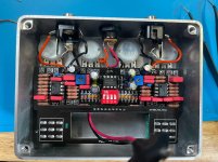
Im baffled.. My LEDS turn on correctly, but there is literally 0 sound.
I looked for shorts, nothing. I reflowed and still nothing.
Do you have Sound in Bypass mode?Yep, I did wire it the way described.
Im baffled.. My LEDS turn on correctly, but there is literally 0 sound.
I looked for shorts, nothing. I reflowed and still nothing.
What voltage are you getting at Pin 8 on both JRC4580D's ???
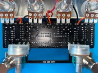
We need to see the back of the PCB board!!!
We do need you to respond to the Questions!Do you have Sound in Bypass mode?
What voltage are you getting at Pin 8 on both JRC4580D's ???
We need to see the back of the PCB board!!!
Do you have Sound in Bypass mode?
What voltage are you getting at Pin 8 on both JRC4580D's ???
We need to see the back of the PCB board!!!
Raspymcnasty
Active member
Thank you for the feedback.
My pedal has 0 sound in bypass and 0 sound when activated. I get a popping noise when i activate the yellow side, but no sound when pop when i activate the red side. However, both leds light up.
For continuity, I get continuity for all points, however, I do get continuity to ground from yellows and purples.
Seems like I may have a short somewhere then?
JRC4580 (Left):
1: 8.669
2: 8.68
3: 7.88
4: .001
5: 8.54
6: 8.562
7: 8.522
8: 17.103
JRC4580 (Right):
1: 8.621
2: 8.625
3: 7.833
4: .001
5: 8.49
6: 8.508
7: 8.473
8: 17.000
Clean those Nine pins !, The Board also needs a Clean.
Pull your Footswitch Adapter Board from the Main PCB & Test the Matching circles again.
If you have Continuity to Ground from Yellows and Purples its the Main Board!
Make sure all your Potentiometers are 1/2 way on rotation!
If not, It's the Footswitch Board.
Raspymcnasty
Active member
Ok so i just clipped the header pins and took off the footswitch board from the mainboard.Clean those Nine pins !, The Board also needs a Clean.
Pull your Footswitch Adapter Board from the Main PCB & Test the Matching circles again.
If you have Continuity to Ground from Yellows and Purples its the Main Board!
Make sure all your Potentiometers are 1/2 way on rotation!
If not, It's the Footswitch Board.
I just went through the continuity test again and it appears i no longer get the continuity from ground to yellows/purples.
However, for the yellows I’m not getting continuity from Out1(yellow) to the 1M nor to the In2 (yellow). But i do get continuity from In2 to 1M.
I want to mention thank you for replying so quickly, I am very grateful for your assistance.
Edit* stupid me, out1 would have to be connected via footswitches to in2.
Is there anything else you see amiss before i use 2 more footswitches?
Last edited:
Big Monk
Well-known member
Ok so i just clipped the header pins and took off the footswitch board from the mainboard.
I just went through the continuity test again and it appears i no longer get the continuity from ground to yellows/purples.
However, for the yellows I’m not getting continuity from Out1(yellow) to the 1M nor to the In2 (yellow). But i do get continuity from In2 to 1M.
I want to mention thank you for replying so quickly, I am very grateful for your assistance.
Edit* stupid me, out1 would have to be connected via footswitches to in2.
Is there anything else you see amiss before i use 2 more footswitches?
So you have proper continuity from the 9 main board pins to the corresponding places on the main board?
Have you also checked the 9 pins on the breakout board to their places on the footswitches?
Don’t mangle the board getting switches off until you are sure.
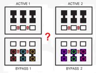
As Big Monk said, With both Footswitch's in Bypass & Active modes , Test each Footswitch Pad for Continuity to see if Solder underneath is touching lug next to it that is causing short.So you have proper continuity from the 9 main board pins to the corresponding places on the main board?
Have you also checked the 9 pins on the breakout board to their places on the footswitches?
Don’t mangle the board getting switches off until you are sure.

Raspymcnasty
Active member
So i did the continuity test for the 3pdt stomp switches, they’re both shorting, i used too much solder unfortunately. But good news is the main board is good to rewire. I’ll just order some new 3pdt switches and try again.So you have proper continuity from the 9 main board pins to the corresponding places on the main board?
Have you also checked the 9 pins on the breakout board to their places on the footswitches?
Don’t mangle the board getting switches off until you are sure.
Thanks for the help!
Yes, it looks like a lot of solder & heat on those footswitch pads.Check for Continuity on these Matching Circles from matching Pin Pads on Adapter Board with Footswitch's:
View attachment 17983
Are you going to reuse the Adapter Board or Wire the individual Footswitches
When soldering Footswitch or Toggle switches, never Solder next to each others pad, skip one & wait for each one to cool!!!
Raspymcnasty
Active member
the bypass quadrant on the right are all showing continuity even when active is switched. I now learned that you can damage a switch by heat.From the photos the switches don't look poorly soldered. What do you mean when you say they are shorting? These switches can be prone to too much heat. If they did get too hot when you soldered them then they may be faulty.
Raspymcnasty
Active member
Im going to just wire them manually, I dont even know how i would desolder the footswitchesYes, it looks like a lot of solder & heat on those footswitch pads.
Are you going to reuse the Adapter Board or Wire the individual Footswitches
When soldering Footswitch or Toggle switches, never Solder next to each others pad, skip one & wait for each one to cool!!!
Big Monk
Well-known member
the bypass quadrant on the right are all showing continuity even when active is switched. I now learned that you can damage a switch by heat.
I've damaged enough switches to know you have to get in there hot and fast, with just enough solder to fill the pads and no more, and work in a pattern like tightening a pipe flange.
I do corners, then the middle, then a diamond.
Similar threads
- Replies
- 29
- Views
- 790
- Question
- Replies
- 16
- Views
- 533
- Replies
- 5
- Views
- 480
- Replies
- 17
- Views
- 659


