Passive AB with 2 LEDs (or a bicolor) - how do YOU wire them?

MBFX

Well-known member
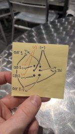
Someone on a FB pedal group posted a question regarding making a small, passive AB switch. They used a 3PDT, and it seems like that is unnecessary when you could just do what I diagrammed in the attached photo. How do YOU like to wire these things?
 

Attachments

  • FB_IMG_1702694054920.jpg
    FB_IMG_1702694054920.jpg
    111.5 KB · Views: 23
Unless its an momentary switch I always use 3PDT stomp switches for things like this - I like the consistency of the clicking action between builds and I always have them on hand. Your diagram is right, but it’s one less (rather bulky) part to have to keep on hand.
 
Unless its an momentary switch I always use 3PDT stomp switches for things like this - I like the consistency of the clicking action between builds and I always have them on hand. Your diagram is right, but it’s one less (rather bulky) part to have to keep on hand.

It looks like the premium DPDT stomp switches from Love My Switches save about 2mm of space, which is relatively huge in a 1590LB. Gives more room for the LED bezels and TS jacks. The builder on FB was having trouble getting everything to fit cleanly.
 
Hi there,

I recently wanted to build something similar, a loop selector. Like the MXR M-144, but better :)

I found the website "General Guitar Gadgets". They have a shop, too, but they also have lots of schematics/instructions on how to wire up all sorts of switchers. The one I used for the loop selector was this one (link to PDF).

Maybe just browse their website to see if there's anything that suits your appetite. Here's some links for you:

https://generalguitargadgets.com/effects-projects/boosters/effects-loop-switch-boxes/
https://generalguitargadgets.com/effects-projects/boosters/effects-order-switcher/

As far as my loop selector goes I like that the pedal grounds the "Send" of the unused loop. I take it that's responsible for the pedal not making popping sounds when switching between the two loops. So there's no need to add any pull down resistors.

I use it to switch between my clean sound and my dirty sound with only one button. I love it. I basically followed GGG, but I didn't add the LEDs. I don't care for LEDs on this pedal and this way I can get away with only a 3PDT instead a 4PDT. And I didn't connect the grounds from the left side (Output, Return 1 and 2) to the right side (Input, Send 1 and 2) because I'm thinking it's not needed. Anyway, it works like a charm.
I made the ABY w/LEDs from GGG. I also made/use their active and passive DI boxes. Great resource!
 
Someone on a FB pedal group posted a question regarding making a small, passive AB switch. They used a 3PDT, and it seems like that is unnecessary when you could just do what I diagrammed in the attached photo. How do YOU like to wire these things?

In your drawing, do you have the - leg of the LEDs going to the sleeves of the jacks as well as the poles of the switch?
 
No, the LEDs and switch connect to the power connector negative. A second, parallel lead from the power connector negative connects the sleeves.
 
Last edited:
Back
Top