problem with Q3 on the ocelot octaver

Hello
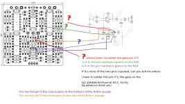
I have problem with the PCB and the pin2 (the gate) on the Q3 I lost the soldering connection


I uploaded on my dropbox a video to show the problem

here is the link https://www.dropbox.com/s/i7yxhjnf78myuqk/20230628_215748.mp4?dl=0


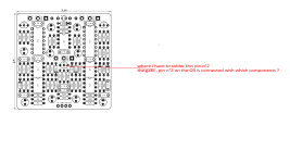
As demanded on the jpg "ocelot Q3pin2" can someone show me where i have to solder the pin 2 of the Q3 on which component ?
1688685590232.png
as it's not working (like you can figure out with the dropbox video) i thought it was the Q1 Q2 Q3 ..i replace the IC6 and IC27. but i damaged and screwed a pad because i tried to remove the Q3 and i lost the connection circuit on the pin2 of the Q3

so i d like to know where the connection on the pin2 on the Q3 goes to make the "original" electric connection

if someone can test the connection with a multimeter when the pedal is off and tell me where i have to solder it exactly to make like the original pcb ...i will repair by making some a"bridge"

another question : do you think that the germanium diodes are fragile ? because i think that the pedal has got a "moderate" hit but a smack

when i mounted the first time it was working perfectly but i would like to change the jack locations on the enclosure and when i tried to replace the pcb on the enclosure, nothing worked anymore

by advance, thank you


BEST
 
Hello
I have problem with the PCB and the pin2 (the gate) on the Q3 I lost the soldering connection


I uploaded on my dropbox a video to show the problem

here is the link https://www.dropbox.com/s/i7yxhjnf78myuqk/20230628_215748.mp4?dl=0


As demanded on the jpg "ocelot Q3pin2" can someone show me where i have to solder the pin 2 of the Q3 on which component ?
View attachment 51925
as it's not working (like you can figure out with the dropbox video) i thought it was the Q1 Q2 Q3 ..i replace the IC6 and IC27. but i damaged and screwed a pad because i tried to remove the Q3 and i lost the connection circuit on the pin2 of the Q3

so i d like to know where the connection on the pin2 on the Q3 goes to make the "original" electric connection

if someone can test the connection with a multimeter when the pedal is off and tell me where i have to solder it exactly to make like the original pcb ...i will repair by making some a"bridge"

another question : do you think that the germanium diodes are fragile ? because i think that the pedal has got a "moderate" hit but a smack

when i mounted the first time it was working perfectly but i would like to change the jack locations on the enclosure and when i tried to replace the pcb on the enclosure, nothing worked anymore

by advance, thank you


BEST
Not familiar with this circuit but you should be able to use the schematic and check for continuity maybe? It may be hard if you lost a trace though. Maybe it’s possible to see where the trace goes on the board itself?
 
Not familiar with this circuit but you should be able to use the schematic and check for continuity maybe? It may be hard if you lost a trace though. Maybe it’s possible to see where the trace goes on the board itself?
that's what i tried to do but i failed so that s why i asked help here and demanded to someone who has built and got this circuit to show me where i have to cnnect the pin2 of the Q3..i thought it should have been easy to give me the exact location !!
 
So R19 is connected to Q3's gate and to ground. So if you figure out where R19 is (which should be trivial) you can check continuity between either lead and ground. Once you found the lead connected to ground, you know that the other lead should connect to Q3's gate. I hope that helps!
 
So R19 is connected to Q3's gate and to ground. So if you figure out where R19 is (which should be trivial) you can check continuity between either lead and ground. Once you found the lead connected to ground, you know that the other lead should connect to Q3's gate. I hope that helps!
i tried to connect the gate of Q3 at the two leads of the R19 but nothing changes..

as i asked.. : do you think that the germanium diodes (or another components ) could have been damaged with a hit bacause the pedal fell to the ground
i replaced the IC6 IC7 and the three Q1 Q2 Q3

for the low price, i will make an order and replace the diodes
 
Last edited:
Yeah “demand” implies that you are entitled to something so it may come off a bit rude. No worries tho, I assume English is not your first language? It’s my second as well.
okay thank you for the vocabulary precision 😉 i didnt want to seem rude.
so if i well understand music6000 just came to proofread the vocabularity issues but didnt give some electronic advises ..hahahaha
 
demand does not mean " ask" ?
is it rude ?
"Ask" is a nice way of requesting help / an answer / questioning ... to which someone else can/may respond to the "ask" (or may not respond, they are not required to respond).

"Demand" is extremely forceful.

If you see someone begging in the street for money, they are asking for money but you aren't obligated to give them any.
A mugger in an alleyway will demand you give your money/wallet/credit-cards/jewellery/watch/etc... and the mugger likely has a weapon so you don't have much choice but to give the mugger everything demanded of you.


Germanium diodes are mostly in glass-case packages, so there's a good chance they're broken when you dropped the pedal, especially if it was open/you were working on it when you dropped it.

Music6000 is a very knowledgeable and helpful contributor on the forum here, by the way.

@fredk2_net13 — What will really help you get better help from other people here is to post some photos of your build.
okay thanks dude for your help to define the term demand and when i should use it 😉

for the pics, i posted a dropbox video
the first time i assemblied and soldered this pedal and it was working
okay i will change the diodes
 
I have recently built one of these and should be able to give you some help. Mine is on my pedalboard though and I need it tomorrow. After that though I can take it off the board for a bit. One thing I do notice from your video is that you are playing chords into it. That will never work. It is strictly for a single note at a time.

If you have a multimeter I would try testing the diodes in circuit. You may not get good test results due to the rest of the circuit, but I always try and test before pulling components as you can damage the components and/or the PCB during removal. I try not to remove anything unless I an pretty sure it is the problem.
 
hi
I have recently built one of these and should be able to give you some help. Mine is on my pedalboard though and I need it tomorrow. After that though I can take it off the board for a bit. One thing I do notice from your video is that you are playing chords into it. That will never work. It is strictly for a single note at a time.

If you have a multimeter I would try testing the diodes in circuit. You may not get good test results due to the rest of the circuit, but I always try and test before pulling components as you can damage the components and/or the PCB during removal. I try not to remove anything unless I an pretty sure it is the problem.
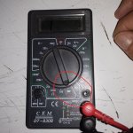
okay...for testing the diode i ve only got a basic multimeter to test like the one i posted


D100 158
D1 252
D2 247
D3 570
D4 570
D5 570
D6 573
i dont know what is measured with this result but here are the numbers i read

are these values correct for you ?


when i built it on the first time it was working and i played only one note its not a polyphonic octaver
but today, it does not work even if played only one note

thank you 😉
 

Attachments

  • 20230709_003841.jpg
    20230709_003841.jpg
    594.5 KB · Views: 2
Last edited:
Back
Top