fredk2_net13
Member
Hello
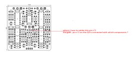
I have problem with the PCB and the pin2 (the gate) on the Q3 I lost the soldering connection
I tried as marked on the jpg to solder to the R20 and the R19 (blue and orange threads) but nothing changed and it still doesn’t work
Can someone tell me please where the 3 pin are linked espacially ht epin2 the gate but if uou can also tell me if my schema is correct
can someone test that with a multimeter..i wrote to pedalpsb but no one respond me
by advance thank you

I uploaded on my dropbox a video to show the problem on the attached files
here is the link https://www.dropbox.com/s/i7yxhjnf78myuqk/20230628_215748.mp4?dl=0
As demanded on the jpg "ocelot Q3pin2" can someone show me where i have to solder the pin 2 of the Q3 on which component ?
by advance, thank you
I have problem with the PCB and the pin2 (the gate) on the Q3 I lost the soldering connection
I tried as marked on the jpg to solder to the R20 and the R19 (blue and orange threads) but nothing changed and it still doesn’t work
Can someone tell me please where the 3 pin are linked espacially ht epin2 the gate but if uou can also tell me if my schema is correct
can someone test that with a multimeter..i wrote to pedalpsb but no one respond me
by advance thank you
I uploaded on my dropbox a video to show the problem on the attached files
here is the link https://www.dropbox.com/s/i7yxhjnf78myuqk/20230628_215748.mp4?dl=0
As demanded on the jpg "ocelot Q3pin2" can someone show me where i have to solder the pin 2 of the Q3 on which component ?
by advance, thank you