carlsoncoder
New member
Hi all -
I'm going to start on my first veroboard project - an EQD Black Ash clone - https://dirtboxlayouts.blogspot.com/2020/03/earthquaker-devices-black-ash.html?m=1 Would have preferred a PCB from here but looks like this one doesn't exist yet!
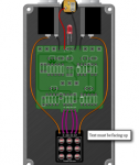
I've done PedalPCB builds before but not veroboard. I understand the onboard wiring, but wanted to make sure I have the offboard wiring correct. I was hoping someone could take a look and let me know if I got this planned right? I am also using the Illuminated 3PDT breakout board from PedalPCB with this and an illuminated 3PDT (this one) as well.

-Justin
I'm going to start on my first veroboard project - an EQD Black Ash clone - https://dirtboxlayouts.blogspot.com/2020/03/earthquaker-devices-black-ash.html?m=1 Would have preferred a PCB from here but looks like this one doesn't exist yet!
I've done PedalPCB builds before but not veroboard. I understand the onboard wiring, but wanted to make sure I have the offboard wiring correct. I was hoping someone could take a look and let me know if I got this planned right? I am also using the Illuminated 3PDT breakout board from PedalPCB with this and an illuminated 3PDT (this one) as well.

- Input Jack
- Tip to Pin 1 on 3PDT breakout (Left of “IN”)
- Sleeve to Ground (Row B or J on board)
- Output Jack
- Tip to Pin 6 on 3PDT breakout (Right of “OUT”)
- Sleeve to Ground (Row B or J on board)
- DC Power Jack
- + to 9v (Row A on board)
- - to Ground (Row B or J on board)
- Input (C1 on board) to Pin 2 on 3PDT breakout (“IN”)
- Output (Pin 2 of Level Pot) to Pin 5 on 3PDT breakout (“OUT”)
- Pin 3 of 3PDT breakout (“OUT”) to Ground (Row B or J on board)
- Pin 4 of 3PDT breakout (“SW”)
- I think this is unused right? Looking at the PCB examples, it just looks like SW breaks the ground for the LED on the PCB. However, since I have my LED right inside the footswitch, that board should handle switching the LED on/off, and I wouldn't need the SW pin to be wired to anything? Or does this get wired to 9V on the board (Row A) so it can power the LED?
- Also for using a CLR (website recommended 470 Ohm) - can I just solder that across the legs of the LED pins once it's soldered to the breakout board?
-Justin


