Schematics 101: How To Determine Which Resistors Bias Each Transistor?

Ginsly

Well-known member
Apologies - I'm in "boot camp" mode and still learning schematics. And everything else...

This may help: how can I determine which resistors in a given schematic are biasing each transistor?

I've been working from Vero diagrams too, which I'm sure REALLY spell it out. Still, I'm not sure how to determine this.

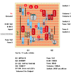
For instance, the (awesome) Fig Buster. I built one based on @music6000 's Vero diagram, but I think I'd like to add a transistor bias/gate knob to cut down on noise when Fuzz and 8-Bit are cranked. What am I looking for here?
Screen Shot 2023-12-28 at 8.34.42 PM.png
 
I’m not super familiar with vero, but iirc I see two resistors connected to the collector and emitter, respectively. The emitter one is 2K to ground, which determines closed loop gain. The collector one also 2K but iirc it’s connected to Vcc via a 10R resistor. The 2K one determines the transistor’s operating point (bias). Others please correct me since I never use vero.
 
Oh I think that 1M resistor is also biasing the transistor (connected from Vcc to the base), but I wouldn’t touch that.
 
Thanks @giovanni - you're talking about Q2? I assume that's the one I'd need to be biasing in order to gate the signal.

I've noticed that "gating/pinching-style" transistor bias pots usually focus on Q2, but I'm really not sure. I also don't know how that works in a 3-transistor circuit. This would also be good to know, in addition to how to identify the biasing resistor on a schematic or vero diagram. Some really basic tips on what to look for would be key to understanding schematics generally.

Apologies for the Vero, I'm really more focused on how to locate this point on schematics anyways. I had just been struggling with excessive noise with this build, and figured I'd start here.
 
Oh I didn’t even notice Q2! The two 2K resistors bias Q1. Now I’m trying to figure out how Q2 is biased…
 
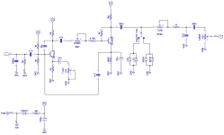
What you've got is a vero layout, not a schematic, just to use the correct terminology. Here's the schematic:
Yep - just didn't have the schematic for this one. Thanks for posting it! I'm actually wondering how to identify the correct biasing resistor on schematics AND Vero layouts. If there is a certain position in relation to Q2 (or Q3 on 3-transistor circuits??) I'd love to know how to find it. I like the sound of it in many fuzz circuits, and it helps cut out noise (which is plentiful due to EMI in my area).

People seem to know right away what resistor should be replaced with a smaller resistor+pot in order to make it an external Bias control. I'd love some tips, as I'm learning schematics bit by bit. I'm two months in - still quite a dum-dum. :)
 
The 10K resistor between the collector of Q2 and Vcc is the bias resistor. You could try experimenting with that to see if you get into gated territory.
 
@giovanni Ah! Ok that's what I thought! Sounds like it's usually the resistor closest to Q2's collector, maybe Q3 in 3-transistor circuits..? By "closest" I mean on the schematic, since technically a 1M resistor is closer to Q2's collector on the Vero diagram. I could be totally wrong about that, though...
 
I believe the gating effect is due to shifting the transistor’s operating point so that the input wave gets cutoff (I’m no fuzz expert tho, don’t quote me!). That can be achieved by increasing the base voltage which can be done by changing the biasing current. You can probably do it on either Q1 or Q2 but it’s more effective on Q2 because that transistor sees a lot more signal (I guess Q3 would work too on a 3 transistor design). The resistor from collector to Vcc controls the biasing current so that’s the one you want to modify.
 
Gotcha, thanks @giovanni! I replaced that 10k resistor with a 1k resistor+ b10k pot, but it didn't yield the under-biased, broken sound I was expecting. It just kind of sounded a little "anemic" and thin at the extreme setting (although it did cut out some noise). I tried a b50k pot too, but same kinda thing happened. Hmm.
 
How did you wire the pot? Have you looked at the schematic for the fuzz factory? That should provide some inspiration.
 
On the fuzz factory the gate is implemented by having a 470R resistor in series with a 10KB pot wired so that the biasing resistor can go from 470R to 10.47K. You have to wire the pot correctly to achieve this. Also keep in mind that the fuzz factory was designed for germanium transistors while I believe the Figbuster is silicon. So I don’t know how close to the same gating effect you will get (again, not a fuzz expert).
 
On the fuzz factory the gate is implemented by having a 470R resistor in series with a 10KB pot wired so that the biasing resistor can go from 470R to 10.47K. You have to wire the pot correctly to achieve this. Also keep in mind that the fuzz factory was designed for germanium transistors while I believe the Figbuster is silicon. So I don’t know how close to the same gating effect you will get (again, not a fuzz expert).
Interesting. I attached a 1k resistor (I’ve kind gathered that’s the minimum you want to use in this situation- ??) to the middle lug of a b10k pot and plugged that into one of the pads where the 10k used to be- I also linked lug 1 to lug 2. Then I hooked lug 3 to the other pcb pad. Is that not correct? I assume it doesn’t matter which lug led to which pad?

I’ll take a look at the Fuzz Factory schematic, but I’m just starting to understand them... Did I not hook up the “bias” pot correctly?
 
That sounds correct to me: pad->resistor->lug2 then lug3 to the other pad.

About the value of the fixed resistor, you may want to experiment with a lower value. The nominal value in circuit is 2K so you can probably go down to 470R (like the fuzz factory) if not lower. And your pot can be lower as well. I would start with a maximum total resistance of about 2K or maybe 3K, which is close to nominal. It would be best to look at a working schematic for inspiration.
 
I'll try that, thanks so much! So what's the lowest I can go without damaging anything?

Could it be that there's another resistor I should be looking at? This seems like the right one, though... hmm
 
I don’t think you’d damage the transistor even if you went down to 0 collector resistance. I would breadboard it to be safe.
 
Back
Top