[Sheepylove] PHewe

szukalski

Well-known member
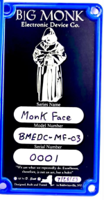
It's still missing the faceplate, but I thought I'd share something which has been on the burner for months now.

Chris is one of my biggest instigators when it comes to pushing my envelope, and I've really enjoyed making some PCBs for some of the more obscure pedals out there (Boss CS-2, TR-2). This is another in that line of layouts.. when I mentioned I was thinking about the PH-1 he told me to run with it and encouraged yet another foray into insecurity.

I'm not usually a big fan of phasers, I enjoy the sound and all, but they're usually too intense for my playing style (the Redstone being the exception).
The PH-1 piqued my interest though. Aion has a PH-1R but that has the resonance feedback which starts getting too wild.

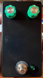
The enclosure is minimal, as is my style. Black washer, because I love a good trolling. There's a faceplate on the way. Green because phasers are green..
1694981576546.png

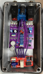
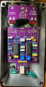
The money shot. I used quad op-amps to let my benefactor work his magic with making it better than the original. I don't know where I had the JRC3403AD from, but they were in the inventory so I used them. I assume they're legit, they work in any case.

Matching the 2SK30A-GR was simple, once I had tested a dozen and found them all in range then I stopped testing. Trim pots are bias and output. There is a volume drop, like the original, and I haven't improved that yet.

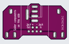
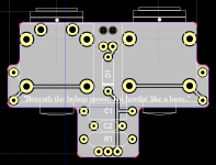
Of (possible) interest is the new revision of the IO board. I reduced the footprint so it won't hit the enclosure lid when used with a 1590B. Plus, it looks like a space ship.
1694981616081.png

Ok, what does it sound like? I have a rough demo, which is the best I can do for now. My main amp is playing up, and the Engl is really only good for heavier stuff. It's phone audio, and a dodgy loop, but you get the point..

 
Killer build and great layout! The black washer is tight too— the black ones are nowhere as unpleasant as the white ones imo, since the black ones are opaque while the white ones have a weird slight translucence to them that cheapens them up.

I’m a fiend for phasers, so it’s no surprise that I love how this one sounds too, but I really do want to emphasize that it sounds rad as heck!

Chris has unknowingly swayed me into starting a Boss clone collection of my own, and I’ve been spending the past two days working on potential names and graphics for each one instead of making progress on my first lithography project, so this is great to see! Keep up the great work dudes! If you want another cool boss pedal or two to clone, the pre- compact-series Roland AP-2 and AP-5 Phasers are both really interesting and don’t have any existing clones— I think I have the schematics somewhere for them, so if you’re interested I could see if I still have those saved anywhere.
 
Nicely done @szukalski ! This thing fornicates 🤘. Chris shared the schematic with me and I’m thinking if you raise the value of r19, you’ll get more gain out of the final output stage of the opamp. Therefore, fixing the volume drop issue. Since you have a 100k volume trimmer to the output jack, you could probably get away with a resistor value of up to 47k. Should be enough adjustment there to get it sounding at unity.
 
That sounds really clean! Great job on the layout! I like how your relay bypass keeps getting smaller… well done.
Very nice- I dig the breakout
Thanks, they're available here if you want to get your own made: https://github.com/szukalski/pedal-simple-relay
I think the only improvement I can make is to make it wider and thinner but it's small enough for me right now.

If you want another cool boss pedal or two to clone, the pre- compact-series Roland AP-2 and AP-5 Phasers are both really interesting and don’t have any existing clones— I think I have the schematics somewhere for them, so if you’re interested I could see if I still have those saved anywhere.
Great idea, I think I have seen the AP-2 around. I'll have to put it in the back-log, it sounds really sweet!

That layout looks killer! I always wanted a PH-1, it's one of the few old boss pedals I never had!
Well, you know where I am if you want to ask.. ;)

Nicely done @szukalski ! This thing fornicates 🤘. Chris shared the schematic with me and I’m thinking if you raise the value of r19, you’ll get more gain out of the final output stage of the opamp. Therefore, fixing the volume drop issue. Since you have a 100k volume trimmer to the output jack, you could probably get away with a resistor value of up to 47k. Should be enough adjustment there to get it sounding at unity.
That's what I played with last night. I took it up to 39k but it wasn't making any difference. I should really get a scope for this stuff though.
 
@szukalski I love what you and Chris are doing on these Boss builds.

Did you do a squared or circular cutout for the PCB DC Jack?
Why not both? I have a double layout for the DC jack, depending on whether you want to have the jack flush with the enclosure (and want/need to cut a rectangular hole) or have it inside the enclosure (my usual M.O. but it doesn't look so pretty). I prefer the round approach, it's quicker. If Tayda were drilling then I'd go rectangular.

Want some gerbers or Diptrace files.. just hit me up.

The design has two drawbacks; 1 - it needs you to snip the jack connector ends off else they hit the enclosure lid (you can also flip it over if the board allows, it's what I usually do, but then the Jack in and out are labeled wrong); 2 - it's not wired for stereo even though the sockets I use are stereo (mainly to avoid confusion, who uses stereo jacks?).

1695037005937.png
 
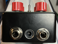
To add to this topic on DC jacks.. this is what the round looks like:
1695037409458.png

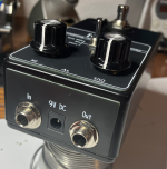
I've also compromised and used a top plate with a massive hole underneath. Not recommended in terms of effort, looks nice though.
1695037452631.png
 
To add to this topic on DC jacks.. this is what the round looks like:
View attachment 56668

I've also compromised and used a top plate with a massive hole underneath. Not recommended in terms of effort, looks nice though.
View attachment 56669

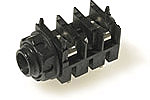
I'm thinking about redesigning my I/O board around the Cliff S1:
1695038891855.png

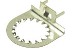
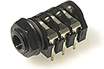
I'm already using the EMI/RFI washer on the Tayda S4 style jack, but I'm foreseeing issues with those jacks in the long term with mis-threading, etc.:

1695038631227.png

When I do this, i'll likely start using a PCB DC jack as well and doing a square hole through Tayda, flush with the enclosure. This is my current design and i want to move away from the header pin attachment in the near future and just do a simple two wire connection to the main board.

1695039011604.png
 

Attachments

  • 1695038566250.png
    1695038566250.png
    25.9 KB · Views: 0
I'm thinking about redesigning my I/O board around the Cliff S1:
View attachment 56672

I'm already using the EMI/RFI washer on the Tayda S4 style jack, but I'm foreseeing issues with those jacks in the long term with mis-threading, etc.:

View attachment 56671

When I do this, i'll likely start using a PCB DC jack as well and doing a square hole through Tayda, flush with the enclosure. This is my current design and i want to move away from the header pin attachment in the near future and just do a simple two wire connection to the main board.

View attachment 56673
If possible, try to have the IO board facing down so you don't run the risk of hitting the enclosure lid:
1695040107041.png
You could also put some OVP onto the IO board if you're running commercially. SMD would be a helpful friend for this and reduce your build time.
 
If possible, try to have the IO board facing down so you don't run the risk of hitting the enclosure lid:
View attachment 56674
You could also put some OVP onto the IO board if you're running commercially. SMD would be a helpful friend for this and reduce your build time.

Funny you should say that because I am using a nameplate on the inside of the lid:

1695041644671.png

And my initial 1.6mm I/O board DID hit the lid. I ordered a 1mm I/O board from JLCPCB last time and that did the trick.
 
Back
Top