Harry Klippton
Not Interested
The image is looking a little smooshed vertically tbhHere is where I stand so far. Just debating whether to have a matte or glossy layer and whether I want to coat the entire face or just the printed areas.

The image is looking a little smooshed vertically tbhHere is where I stand so far. Just debating whether to have a matte or glossy layer and whether I want to coat the entire face or just the printed areas.
Just wanted to point it out now in case there's time to fix it. Be a shame to wreck a cool graphicIt does look better through inkscape but you may be right.
Just looked at the schematic and a teardown video of it. TBH it really is just a triangle muff with a slightly smaller highpass cap (3n3) in the tonestack and different pot values (50K instead of 100K).
The actual Elk is a bit weirder with the tonestack (330p cap instead of the usual 4n one!), and of course being PNP. I feel like the specific one from Wata may in fact have been some factory error. Or just being authentic to the EHX origins and putting in whatever they had kicking around in the factory. Or EQD did in fact just build an ever so slightly different muff and slapped the Boris signature on it.
I get drift, but 10x higher value? I feel like it more likely is a misplaced/mislabelled component ending up in an ultimately more usable tonestack. I mean just put the elk tonestack into the calculator, that thing really notches deep into the mids!EQD stated that the component values in Wata’s Elk had drifted over time. That isn’t surprising. I build an Elk based on the schematic, and while it was definitely in the ball park, it didn’t quite sound like Wata’s. I ended up adding a second 330p in parallel. Now it sounds even closer, though still not quite all the way there. Maybe I should add a third…
There’s a t thread on FSB where it was disassembled and the values recorded.How confident are we in the schematic on the Kit Rae site? It definitely seems like that cap is an error, and every single thing on the internet references that schematic so there is no way to verify it
But was it a single one that has ever been traced or at least a couple? I know the Elk fuzz is a bit more obscure, but if it was just one, there's no way to know which is the correct one, the one on the muff page or the one the Hizumitas is based off.There’s a t thread on FSB where it was disassembled and the values recorded.

 www.wrenandcuff.com

It was a breakdown of the Hizumitas.But was it a single one that has ever been traced or at least a couple? I know the Elk fuzz is a bit more obscure, but if it was just one, there's no way to know which is the correct one, the one on the muff page or the one the Hizumitas is based off.
What knobs are you going to use?I just ordered a Tayda UV print (with gloss) for a purple enclosure that would look like this (circle dots are where the drill holes go). If you're interested I could send you the PDF I uploaded.
(Ignore the white outline around the artwork. I deleted that.)
View attachment 22757
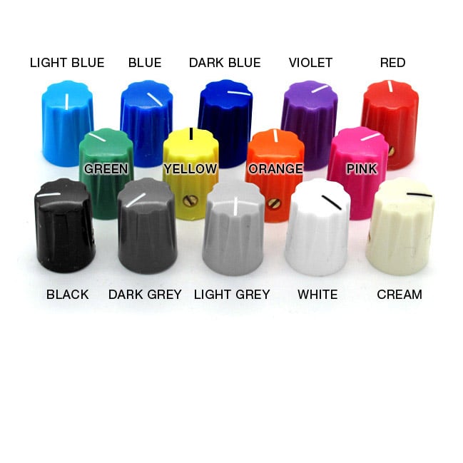
What knobs are you going to use?
Even small ones look like they’ll hide too much of the antlers, which would be a shame on such a great graphic!

It's just the wires that are a bit on the way in the picture, the LED is fine and directly wired to the board.Hey. gila_crisis, what is going on with your power and ground connections there? You're not using the ground pads for the input/output jacks and it looks like you've got multiple wires hooked to the led.