You are using an out of date browser. It may not display this or other websites correctly.
You should upgrade or use an alternative browser.
You should upgrade or use an alternative browser.
Stuff you wanted to know but were afraid to ask
- Thread starter spi
- Start date
swyse
Well-known member
Turns them into BJTs it turns out, can’t recommend.Is there any reason other than difficulty I wouldn’t want to add legs to my smd j201s to use for breadboard and vero board use?
 The writing on this one seemed a little sloppy so maybe it is fake, I’ll retest with my crisper looking ones to see tomorrow.

giovanni
Well-known member
I would just stick with standard values: measure a few and find the closest value to what you need.Is there any reason why I’d want to deviate away from only having E12 resistors?
There are a bunch of odd ball resistors in builds, could I just get away with using the closest from the E12 series? (Or making teepees).
Harry Klippton
Not Interested
How do you measure for drilling off a PCB?
spi
Well-known member
I place the PCB on a paper, then poke a pencil through the holes that need to be drilled (for example the middle of each switch or pot). Then for pots, offset where you made the mark by 16mm. Then I can measure how a far apart each hole is and build a drill template.How do you measure for drilling off a PCB?
Locrian99
Well-known member
Why when I’m building something and set something down, a diode, my wire cutters, a piece of wire, the nut and washer for the jack or pot. I somehow always put it down in the worst possible spot and it takes me forever to find it even though I set it down 30 seconds ago, somehow it ends up under my printed schematic, and 3 bags of resistors. And no the answer isn’t I need to keep a tidier workspace.
KR Sound
Well-known member
This is my life- keys, hat, drink, daughter, everything.Why when I’m building something and set something down, a diode, my wire cutters, a piece of wire, the nut and washer for the jack or pot. I somehow always put it down in the worst possible spot and it takes me forever to find it even though I set it down 30 seconds ago, somehow it ends up under my printed schematic, and 3 bags of resistors. And no the answer isn’t I need to keep a tidier workspace.
KR Sound
Well-known member
KR Sound
Well-known member
Stupid question and I probably already know the answer. If I don’t want to include a battery snap in a box, is it just as easy as not wiring it up and just using a mono input jack? Im thinking yes, right?
And on BYOC boards, I wouldn’t hook up the wire shown to the power Jack and battery snap, correct?
Thanks.

And on BYOC boards, I wouldn’t hook up the wire shown to the power Jack and battery snap, correct?
Thanks.

Robert
Reverse Engineer
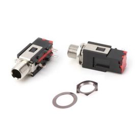
Where tf can I get high quality jacks for the Power I/O module?! I feel like I’ve exhausted the internet looking for 3pin PCB mount jacks that fit the board.
I'm not sure if there's a premium brand, these are the ones I've always used and never had any issues with them.

6.35mm 1/4" Right Angle Stereo Female Connector Thread Lock Panel Mount
Get It Fast - Same Day Shipping

It even says so right here.
Ugh, you mean to tell me I scoured this site for jacks and couldn’t find these, after I accidentally order the wrong ones… welp, I was warned this would happen…I'm not sure if there's a premium brand, these are the ones I've always used and never had any issues with them.

6.35mm 1/4" Right Angle Stereo Female Connector Thread Lock Panel Mount
Get It Fast - Same Day Shippingwww.taydaelectronics.com
View attachment 35153
It even says so right here.
steviejr92
Authorized Vendor
Im afraid to ask literally anything about programming the Terrarium....the fact that i said Terrarium and not Daisy seed lets you know how far i am from attempting it......
iamjackslackof
Well-known member
Those turned out nice! Do you use a sanding block or by hand? Or have any other tricks to it? I never could get an even straight grain going, even with a sanding block.I sanded with 220, 320, 400, and 600 for this one:
Nail the Sandpaper to the Bench & do straight single passes with the Enclosure.Those turned out nice! Do you use a sanding block or by hand? Or have any other tricks to it? I never could get an even straight grain going, even with a sanding block.
steviejr92
Authorized Vendor
Read that and look at his profile picDo these pants make my butt look big?
Robert
Reverse Engineer
Do these pants make my butt look big?
Not at all honey, in fact your butt makes those pants look small!


