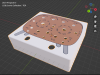
Super Heterodyne layout

DailyDovetails

Well-known member
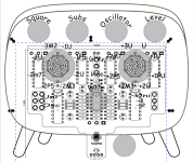
I'm working on a layout for the Super Heterodyne reciever but it has a lot of controls and labels. If you have done one can you take a look and let me know if I have everything labeled correctly?

The offset foot switch on this bugs me but the design doesn't really work unless I move the board down to the bottom of the case. Bonus points if you have a recommendation of something useful I could add on another foot switch to make it symmetrical again.
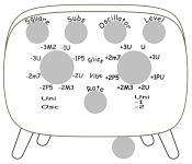
1703002176083.png
1703002196566.png


I'm realizing as I post this that on the right side the +1PU should be +1P5, that is assuming I have those labeled correctly in general.
 
The offset foot switch on this bugs me but the design doesn't really work unless I move the board down to the bottom of the case. Bonus points if you have a recommendation of something useful I could add on another foot switch to make it symmetrical again.

Are you putting it in a 1590bb?

My rec for a second footswitch would be to replace R22 (100r) with a footswitch, with each throw attached to its own 10-20k pot. This will basically give you two presets for the Lag control found on the Schumann PLL, with the third pole of the switch being used for LED indication.
The extra pots / less could be situated between the toggle switches and rate pot to retain symmetry
The box will be one I 3d print the exterior dimensions will be 140x120 with 2mm walls all around. Its double the width of the boxes I typically do. I eventually am going to build a tiered pedal board for the pedals I have made and am intending on using the 70x120mm spacing as kind of a standard so it will look uniform when done.

I read a little bit about that mod so that basically controls the speed of the shift between notes so I could say tune a fast and slow transition mode? I like that idea. I think the idea on the knob placement is good also. I would just need to kick the text for the switches to the outside.

Can't wait to see it when it's finished

Yep!

If you want to get a little saucier, you could use a 4pdt and use the additional pole to also swap C23 from 100n to something like 33n with one of the Lag pots. This will further alter the response of the vco, to give you two very different timbres
 
Can't wait to see it when it's finished

Yep!

If you want to get a little saucier, you could use a 4pdt and use the additional pole to also swap C23 from 100n to something like 33n with one of the Lag pots. This will further alter the response of the vco, to give you two very different timbres
Hmm interesting on the cap change. I see a bit of experimenting in my future with this.

When doing the pot modification at R22 do I need to install a resistor before the pots to retain some amount of resistance there or is it OK with it open?
 
Hmm interesting on the cap change. I see a bit of experimenting in my future with this.

When doing the pot modification at R22 do I need to install a resistor before the pots to retain some amount of resistance there or is it OK with it open?

PLLS are awesome for experimenting with wacky sounds. For that cap, you can play with anything from 100p to around 1u to see what you like the most. 100n and 33n are just the two most common values I've seen in that slot

It's perfectly fine being sent straight to ground, but if you want an easy way to get the stock sound, a 100r in series would be a good idea
That's neat with the caps. I think I will play with it a bit. If it ends up adding a lot of versatility, I could set up a section with switches in parallel and then whatever cap you switch in would add to the base value and could give you a pretty good range with a few switches. I have plenty of room on the left and right sides of the board that is kind of dead area on my design. I'm not opposed to a lot of controls if they do something interesting.
 
This is a different circuit, but it shows a bit of what the Lag and cap Range switches do to the 4046

I'm trying to find the Heterodyne I modded, but it looks like I may have deleted the videos

Edit - I have a MadBean Tone Virus in my queue, so I'll try to get it whipped up tonight or tomorrow with some hacks
 
I'm excited about getting this build together after the video. I think my family will be thankful that I play into the mixer and can use headphones until I get the hang of this. Although even after I get the hang of it I get the sense synth guitar isn't for everyone.

I looked at the data sheet for the 4046 https://www.ti.com/lit/ds/symlink/c...18176&ref_url=https%3A%2F%2Fwww.google.com%2F I'm wondering looking at it if the resistor and cap you reference work similarly to a high pass filter with their effect to the possible range. The cap going between the 2 contacts and resistor to ground. If that is the case I think a on off on switch with the 33n in the center maybe a 10n and then a 68n and a 470n would probably give you a pretty big range. With the pot open I'm wondering if the different caps sound somewhat similar or not. I'm not sure if that is related to how it works here tho. Let me know how your Tone Virus experiments go.

If that setup worked well I could do the switch between the 2 voices and have one pot and one switch each and hopefully cover a lot of range.

Anyone have any feedback on the accuracy of the layout I came up with?
 
This is a different circuit, but it shows a bit of what the Lag and cap Range switches do to the 4046

I'm trying to find the Heterodyne I modded, but it looks like I may have deleted the videos

Edit - I have a MadBean Tone Virus in my queue, so I'll try to get it whipped up tonight or tomorrow with some hacks

I think I came up with a plan for this build. My plan is for the left to be the hopefully practical mild side. It will have the 100r resistor wired before a 10k pot and the switch will have 33n, 100n, and 470n setting, the other side will be the experimental wild side it will have no resistor a 20k pot and 1n, 100n and 1u settings. Thinking it should make a wide variety of sounds. Thank you for all the help with this. The finished layout I came up with is below.

1703134079624.png
 
Back
Top