Tear jerker schematic request

JHKcustoms

New member
I’m getting ready to order parts for this beasty! First wah build so I’m stoked for it.
I know that the build docs arnt up yet but is there anyway you could post the schematic?
Thanks
JHK
 
TearJerker-Schematic.jpg
 
It's a good old Cry-Baby! Pretty much the original circuit, with some trimpots and a DIP switch for the range capacitor. With all of the switches open, this pedal will reach up into dog-whistle territory. I modded my Dunlop Cry-Baby and tweaked most of the stuff that's tweakable here. Stock is about midway on all three trimpots. The LOW trim will affect the bottom end of the sweep range and the gain across the board. The MID trim is pretty subtle. It is important to use quality film caps, except C2 (ceramic or mica), C4 (tantalum) & C100 (aluminum). Get a good WAH pot, Hot Potz, for instance, and take time to properly mechanically align it. A cheap WAH pot will not give the full sweep range and will wear out quickly.

One more thing, this is the unbuffered version of the circuit. When Dunlop took over production of the Cry-Baby in the early '80s, they added an emitter-follower buffer at the front-end because the input circuit does two things that may or may not be desirable:
1) it loads whatever is driving it
2) it is influenced by the output impedance of whatever is driving it
Turning the VOL trimpot clockwise will accentuate both of those factors.
Not a criticism of the circuit design, just a heads-up so you know what to expect.
 
This board has the IN & OUT connectors onboard, the ON/OFF switch and Wah pot are outboard. You can read all of the on-board component values from the silk-screen. You might want to make the Q trimmer an external pot and the DIP switch (or at least part of it) a rotary switch. If you're an experienced build and you know how a Cry Baby goes together, you can figure it out. Otherwise, you should probably wait for the Build Docs.
 
You actually can use the old SPDT switch, but then it's not full bypass. When I modded my Cry Baby, I changed over to DPDT full bypass. These PedalPCB boards are 100x better made than the one in my mid-90s Cry Baby. These are double-sided, have a ground plane & thru-plated holes.

If you're a fan of Pink Floyd, you've heard the song Echoes and may have wondered how Mr. Gilmour got that spacy seagull wail near the middle of the song. It's done with one of these. You have to hook it up backwards and use the guitar's volume & tone knobs along with the wah pedal to modulate the pitch, timber and volume. Be sure to hook up a delay too.
 
Last edited:
thanks for diagram! is there a dispswitch combo that's the most "stock" crybaby wah-like? i'm having trouble getting a smooth sweep. feels like the bass is accentuated and the mids aren't super present. Played with the trimpots a bit last night and it's getting close, there's just so many options haha. Didn't know if there was a good "jumping off" point.
 
The standard range capacitor is 10nF, which is the setting PedalPCB gave above. Set the Vol, Low and Mid trimpots to the middle and the Q pot to 9 o'clock and you'll be close to the stock settings. Alignment and taper of the Wah pot is critical. Which pot did you use?
 
I'll set those, thanks! I used the Chase Tone Tru-talk 100k pot. I have a stock crybaby pot from a dead slash wah I cannibalized some parts from as well if this doesn't work out, including the red fasel inductor.
 
The recommended wah pot alignment is with the pot just at the end of the travel when the pedal is in the toe-down position. The treble end of the travel is more sensitive, so that's the one you want to get right. Use the DIP switch to set the range and the LOW pot to fine tune the bottom end.

Fulltone shows how to align wah pot
 
Last edited:
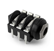
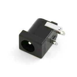
I've never made a Wah before and have this board. Which PCB mounted DC jack does it require with the Smallbear enclosure? And I'm assuming the 6 pin Neutrik style 1/4" PCB mount jacks work too? these...
 
That's the correct 1/4" jacks.

This is the DC jack I used:

You can use whatever wah pot you choose, depending on how much you want to spend on one. For prototyping I used a generic 100K wah pot from Smallbear in mine, but you might want to get something a little nicer. I believe this is what I used:

For the inductor I used a Fasel inductor from a gutted Crybaby... again, there are a lot of options here.
 
Is there any way to put the dip Switch rather on a Rotary to make it an extern control ?

What would be the type of Rotary and wiring ?
 
Get a 1P9T (9 position) rotary switch. Small Bear sells a 1P12T switch (p/n 0227A). That's what I used on my Cry Baby upgrade. The rotary switch has a stop tab washer that you can move to set how many positions you can select. We will use 9 positions. First thing we do is install different caps for C8 - C16. I'll recommend that we pick caps such that you can select pedal ranges that are 2 octaves up and 2 octaves down from the stock range. The rotary switch will go in approx. 1/2 octave steps. Here are the new capacitor values:

C8​
470pF​
C9​
470pF​
C10​
1.5nF​
C11​
3.9nF​
C12​
10nF​
C13​
22nF​
C14​
47nF​
C15​
100nF​
C16​
220nF​
Note that C8 is always in the circuit and one of the other caps is in parallel with it, except for when the rotary switch is full CW, then no cap is in parallel with C8. If you want a different range on the rotary switch, here's how to pick the cap values: Stock is 10nF. Doubling the cap value moves the range down 1/2 octave. Halving the cap value moves the range up 1/2 octave. 2 octaves each way is quite a bit of range and you might not use all of that range. Bass guitarists will love the low end of the range switch. By comparison, the Cry Baby 535Q has a 6 position rotary switch and the cap values range from 1.2nF to 27nF. These cap values vield a range less than ±1 octave, which I think is too small of a range. The GCB-100 Bass Cry Baby has a 68nF range cap. Remember that C8 is in parallel with the other caps when calculating cap values.


Set the stop tab washer so that you get 9 positions on the switch and temporarily install the nut on the shaft to hold the stop tab washer in place. Use a DMM to figure out which pins are which on the rotary switch. The rotary switch's common terminal is the one near the center. We'll call pin 1 the one that is selected when the switch is full CCW. Make a mark with a sharpie next to that pin. Wire the rotary switch to the board as follows:

RotaryDIP sw
C16
18
27
36
45
54
63
72
81
9not connected
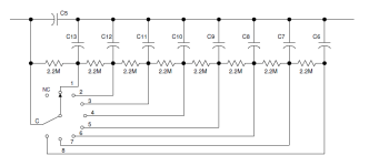
One more thing: the rotary switch will pop a bit when you switch it. If you don't want it to do that, install eight 2.2M resistors where the DIP switch goes, then attach the rotary switch wires to the resistor leads.
 
Last edited:
Back
Top