Bricksnbeatles
Member known well
I've got a Tonebender MK3 that I built a few years ago on a Fuzzdpg board when I was first starting to, but never boxed up. I modded it to have an external bias on q3 for a greater range of tones by replacing R9 with a 10K pot in series with a 1k resistor.
I revisited it and I'm not making sense of the voltages I'm getting:
Q1
C -3.5V
B -1.59V
E -1.5V
Q2
C -3.5V
B -1.49V
E -1.4V
Q3 [Bias cw/100% (11K)]
C -101mV
B -60mV
E 0v
Q3 [Bias ccw/0% (1K)]
C -2.8V
B -68.8mV
E 0v
SO... Q1 and Q2 are within the typical expected bias range, but what has me baffled is that when Q3 has the bias fully CCW, so the r9 value is only 1K, I'm getting fairly typical mk3 Q3 voltages, other that the Base voltage which is around 1/10 of what it should be, but whatever. What has me confused is that with the pot fully clockwise so the R9 value is ~11k (just a hair over the typical 10k value), my voltages are absurdly tiny compared to what they should typically be, but the sound I'm getting is more along the lines of what is to be expected of a Mk3, while the tone with the bias pot fully CCW so the R9 value is at 1K is more what you might expect of a TB with a starved Q3. Pretty much, it functions mostly as you would expect (the range of the bias pot isn't what I was hoping for, so I might sub some stuff so I can get a wider range of voltages on Q3-- at the time I was trying to get more of a gated sound like when the balance is down low on a buzzaround), but the voltages make no sense. thoughts?
Am I correct in being confused by this, or does everything make sense and I'm just confusing myself by once again working on pedal stuff late at night when I should be catching up on sleep?
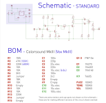
Schematic and sound clip (with timestamps for different fuzz and bias levels) below

0:01- Bypass
0:15- Fuzz 100%; Tone 50%; Bias 100%
0:35- Fuzz 100% Tone 50%; Bias 0%
1:07- Fuzz 0%; Tone 50%; Bias 100%
1:24- Fuzz 0% Tone 50% Bias 0%
1:44 Fuzz 0%; Tone 50%; Bias sweep from 100 to 0
1:52 Fuzz 100% Tone 50%; Bias sweep from 100 to 0
2:16 Fuzz 0%; Tone 100%; Bias sweep from 100 to 0
2:27 Fuzz 100%; Tone 100% Bias sweep from 100 to 0
2:43 Bypass again
I revisited it and I'm not making sense of the voltages I'm getting:
Q1
C -3.5V
B -1.59V
E -1.5V
Q2
C -3.5V
B -1.49V
E -1.4V
Q3 [Bias cw/100% (11K)]
C -101mV
B -60mV
E 0v
Q3 [Bias ccw/0% (1K)]
C -2.8V
B -68.8mV
E 0v
SO... Q1 and Q2 are within the typical expected bias range, but what has me baffled is that when Q3 has the bias fully CCW, so the r9 value is only 1K, I'm getting fairly typical mk3 Q3 voltages, other that the Base voltage which is around 1/10 of what it should be, but whatever. What has me confused is that with the pot fully clockwise so the R9 value is ~11k (just a hair over the typical 10k value), my voltages are absurdly tiny compared to what they should typically be, but the sound I'm getting is more along the lines of what is to be expected of a Mk3, while the tone with the bias pot fully CCW so the R9 value is at 1K is more what you might expect of a TB with a starved Q3. Pretty much, it functions mostly as you would expect (the range of the bias pot isn't what I was hoping for, so I might sub some stuff so I can get a wider range of voltages on Q3-- at the time I was trying to get more of a gated sound like when the balance is down low on a buzzaround), but the voltages make no sense. thoughts?
Am I correct in being confused by this, or does everything make sense and I'm just confusing myself by once again working on pedal stuff late at night when I should be catching up on sleep?
Schematic and sound clip (with timestamps for different fuzz and bias levels) below

0:01- Bypass
0:15- Fuzz 100%; Tone 50%; Bias 100%
0:35- Fuzz 100% Tone 50%; Bias 0%
1:07- Fuzz 0%; Tone 50%; Bias 100%
1:24- Fuzz 0% Tone 50% Bias 0%
1:44 Fuzz 0%; Tone 50%; Bias sweep from 100 to 0
1:52 Fuzz 100% Tone 50%; Bias sweep from 100 to 0
2:16 Fuzz 0%; Tone 100%; Bias sweep from 100 to 0
2:27 Fuzz 100%; Tone 100% Bias sweep from 100 to 0
2:43 Bypass again

