Twin Face issues

jwyles90

Well-known member
Hey all,

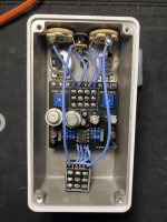
Just put together a Twin Face build recently and while it technically "works", it's making some weird noises in the process. The silicon side is super noisy, and has a decent amount of hiss in the noise floor. For both silicon and germanium, if my guitar volume knob is at anything less than 10 there's basically no signal that comes through, and if I roll the volume all the way down on the guitar it just makes this loud buzzing noise instead of no noise at all. I thought initially it might be the guitar itself, but I tried it with multiple and the issue was present each time. I also noticed that it does something similar with my guitar tone knobs. Rolling them down to zero actually makes the signal sound more intense somehow, while anything in between doesn't seem to have a discernable difference from 0 to 10.

Any thoughts on what could be causing this? I know that fuzz faces can be kinda finicky at times, but this feels a little too finicky...
IMG_8923.jpeg
 
What kind of voltage readings are found at the input supply, pin #5 on the chargepump, and the BJT collectors? I'm guessing you've adjusted the biasing trimmers for each side. (?)
 
What kind of voltage readings are found at the input supply, pin #5 on the chargepump, and the BJT collectors? I'm guessing you've adjusted the biasing trimmers for each side. (?)
So I just took some readings, the germanium side I was able to bias to -4.5v (I had just biased it by ear previously). The silicon side I'm only getting 8.9-9v readings on the collector, regardless of what I do to bias it. Same with pin #5 on the chargepump.
 
You're reading positive 8.9-9V on the chargepump at pin #5 ???? It should be (negative) -9V

If pin #5 on the chargepump is a positive voltage, the chargepump may be bad.
 
You're reading positive 8.9-9V on the chargepump at pin #5 ???? It should be (negative) -9V

If pin #5 on the chargepump is a positive voltage, the chargepump may be bad.
Oh yea sorry, it’s -8.9-9v. Need to get better about specifics when troubleshooting.

If I’m unable to get any voltage change when biasing the silicon transistors, could the trim pot be the issue?
 
Oh yea sorry, it’s -8.9-9v. Need to get better about specifics when troubleshooting.

If I’m unable to get any voltage change when biasing the silicon transistors, could the trim pot be the issue?
It's possible. Measure the collector voltage at both extremes of that trimmer's sweep.
 
Like Big Monk says . . . . reflow around the trimmer and Q2. Clean up any excess flux. Use a magnifying glass to check your joints. If everything pans out after a reflow and joint exam, but the problem persists, it may be that the trimmer needs replacing.
 
Like Big Monk says . . . . reflow around the trimmer and Q2. Clean up any excess flux. Use a magnifying glass to check your joints. If everything pans out after a reflow and joint exam, but the problem persists, it may be that the trimmer needs replacing.
Thanks for all your help! I think I’ll have some time in the next couple days to take a whack at it. I’ll report back with the results after reflowing
 
Like Big Monk says . . . . reflow around the trimmer and Q2. Clean up any excess flux. Use a magnifying glass to check your joints. If everything pans out after a reflow and joint exam, but the problem persists, it may be that the trimmer needs replacing.
Check your solder joints. That ain’t right. Focus around Q2 collector.
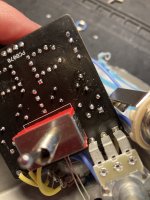
Alright so I went back and double checked all my joints. They all looked pretty solid to me but I reflowed them regardless. Still not getting anything other than 8.9v through the duration of the trimpot’s sweep. Ill probably replace the trim pot when I have some more time, but here’s the underside of the board after reflowing in case there’s something there that I’m not seeing:
 

Attachments

  • FE0F1700-44F1-49F8-933E-DBB077220867.jpeg
    FE0F1700-44F1-49F8-933E-DBB077220867.jpeg
    376 KB · Views: 4
I've had several pots in the past year defective...... several trim pots as well... Now I get in the habit of testing each ones sweep with a multimeter before I solder them in... only takes a second to test them
 
Hey all,

Just put together a Twin Face build recently and while it technically "works", it's making some weird noises in the process. The silicon side is super noisy, and has a decent amount of hiss in the noise floor. For both silicon and germanium, if my guitar volume knob is at anything less than 10 there's basically no signal that comes through, and if I roll the volume all the way down on the guitar it just makes this loud buzzing noise instead of no noise at all. I thought initially it might be the guitar itself, but I tried it with multiple and the issue was present each time. I also noticed that it does something similar with my guitar tone knobs. Rolling them down to zero actually makes the signal sound more intense somehow, while anything in between doesn't seem to have a discernable difference from 0 to 10.

Any thoughts on what could be causing this? I know that fuzz faces can be kinda finicky at times, but this feels a little too finicky...

View attachment 45514
Are you switching the Toggle, you can only bias the Transistors when toggle is set to each side or you will get full voltage readings!?
 
Are you switching the Toggle, you can only bias the Transistors when toggle is set to each side or you will get full voltage readings!?
Oh my god...
I didn't even think to do that when I was checking before. I read your comment after replacing the trim pot (which was a feat in and of itself) and got it biased correctly. however, the issue is still there. Super hissy when the silicon side is on, and then when I have the volume on my guitar rolled back there's no signal and just hiss. When the volume is all the way down it just sounds like a ground hum is happening.
 
Which NPN transistors did you use? If they are old euro types, they might be CBE instead of EBC.
I pulled them from a bag I had. Not sure where exactly each one came from, but Q1 is a CDIL BC108C with M5 marked on the side. Q2 is the same but with MD on the side instead.
 
Do you have a way test them?
Is there a way to do that with a DMM? Otherwise I’m not sure I do. I did socket them though, so I suppose I could try putting different transistors in there to see if that made a difference.

When I’m on the germanium side the weird “ground hum when the guitar volume is all the way down” thing happens as well, if that makes a difference at all.
 
Back
Top