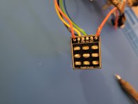
They do look pretty destroyed, but I would check with a multimeter for continuity between the pads and the 3pdt to ensure that you in fact have dead pads, or that it is one, the other, or both pads. You can also just insert your LED into the pads in both orientations and turn on the pedal to see if you get some light.
It was most likely installed incorrectly, as the wiring diagram of a circuit other than the tyrian on the tyrian build docs misleadingly shows the LED long leg (anode) going into the square pad, which is the opposite of the current norm at PedalPCB (The LED long/anode/a/+ goes into the round hole, the short/cathode/k/- leg into square hole).
I'm not sure why the norms for diodes are like that--non-LED diodes also have the -/cathode/k end in a square pad-- since square pads always require the long/positive leg for capacitors--maybe to do with current flow? Or even why you would need square pads to begin with other than being able to visually allocate specific solder points to the poles of polarized components.
As far as I can tell, the line with the resistor is your hot line, the other line goes to ground, and the loop between the two is connected via the middle column of the first and second rows of the 3pdt (the connections labeled "switch" and "ground" on the daughterboard--your yellow and green wires). You might want to check continuity between those lugs and between those pads, just to make sure it's not an issue in the daughterboard.
Those connections are conveniently made for you in the PCB, but if the traces are irreparably damaged within the PCB, you will have to find a way to connect them outside of it and to the 3pdt so the light circuit switches with the signal.
Luckily, since the LED circuit is independent and only shares power and ground with the rest of the board, it shouldn't be too hard. If your pads are indeed dead, you could jumper the resistor to the long leg of the LED and the short leg to the yellow switch wire going into your little 3pdt daughterboard. Then, you could extend the green wire from the daughterboard directly to the ground of the "in" jack.
On the Tyrian landing page, where it shows traces, it looks like the right side of r4 is getting the 9v from pin 8 of IC1, and the left side is going to the LED anode. I would maybe double check with your multimeter which end of the resistor is receiving the incoming 9v and which is emitting the modified or resisted current, because I've burnt out a couple LEDs with straight 9v.