Valhalla build

RobertJay

Member
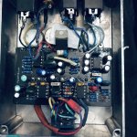
So, this isn't my first PedalPCB build, but the first that actually needs the the footswitch to be wired up to test for sound. I want to use a footswitch pcb with LED wired to the jacks and power supply, then wire that up to the Valhalla. Doesn't look like it's possible the way this circuit wants the jacks wired to the PCB and the mysterious signal path I see. Weird stuff. The input signal goes right to Cap 1 and onto the rest of the signal path... Where does the bypass come from? Not adding up to me.
 
Last edited:
It's a buffered-bypass circuit.

The input jack is directly connected to R1/C1 and buffered by IC1.1.

The Bypass signal comes from the point marked "BUFFER" at C23/R28.


You could ignore this and wire it up for true-bypass, just use IN as the input and PCBOUT (far-right pad at the bottom) as your output.
 
Hey, thanks again, but FYI. Seems that buffer circuit is crucial for this build. This circuit is famously known for a terrible noise when the gain is past 1 or 2 oclock. Having a boss pedal before it makes it quiet, the buffer.... Probably not advisable to recommend bypassing that buffer. I will look into wiring up the pcb as intended while utilizing the 3pdt in the build. I think the initial inquiry was about needing a footswitch just to test the initial circuit build.... I didn't know I definitely should've used that buffer circuit in my final build. Aha!
You should have an updated version of this PCB with the traces rerouted to stop Oscillation that caused the old PCB issues.
Yes, it should be wired as shown in the Valhalla BOM.
 
I wasn't recommending "bypassing" the input buffer, I was just describing how you could wire the circuit for true-bypass.

The input buffer would still be in the circuit when the pedal is active.
 
The PCB was updated in January 2021 so you should have the newest revision.

Pay attention to the routing of your wiring, you want to keep the input wire as far from the PCB as possible.
 
The PCB was updated in January 2021 so you should have the newest revision.

Pay attention to the routing of your wiring, you want to keep the input wire as far from the PCB as possible.
I just got the build to stop making the noise when I moved the input wire out of the way. What's this about? Someone mentioned making sure the wires for the in/out are shielded. Seems this is a thing?
 
Solid core wire and fairly long in out leads no squealing probably one of my if not THE highest gain pedal I’ve put together it has high gain hiss and only if everything is maxed will it squeal ( and sound like shit ) definitely one of my favorite pedals my original 1st build squealed easily with stranded wire and oddly doesn’t with solid core plus you can bend the solid core and place it where you want it
So maybe try some solid core I just never use lengths over say 4 1/2” inches but leave play to service the pedal if need be
I personally have yet to build an effect where shielded wire helped and in no way saying it’s in effective just haven’t had issues to justify using it only in guitar cavities do I.
 

Attachments

  • CD4AD6D8-12E5-4FB9-9171-6246942CDE1E.jpeg
    CD4AD6D8-12E5-4FB9-9171-6246942CDE1E.jpeg
    1.8 MB · Views: 21
Yeah, thanks. I'm only about 2 years into this, only 1 year of actually making and shipping builds. Last year was all RAT, muff and overdrive. Now it's time for high gain and I was not prepared to feel like such a noob again. Haha. I did just that, used the solid wire to bend and shape to stay along the sides and out of the way. That's going to be the fix for another one I just tested last night. High frequency feedback after the tube screamer and through the Mesa dual Rec pre amp circuit.
 
I also found if you use sockets 1 - if you do get the good sockets and 2 - make sure the sockets are soldered well and components are seated well I’ve had issues with both and lost too many hours chasing something stupid on my part
 
From what I call... The Signature Sound Series. As close as someone can get to buying the whole rig. Signature Sound, classic albums, cool stuff. The Valhalla went in the TooLBoX. Mesa Boogie in the Tallica. OpAmp Big Muff and phaser in the pumpkins build. Not so much high gain as it's the album sound. I'm working on a thing or 2...
 

Attachments

  • 20220320_131300.jpg
    20220320_131300.jpg
    682.3 KB · Views: 24
  • 20220320_131336.jpg
    20220320_131336.jpg
    909.3 KB · Views: 22
  • 20220321_213913.jpg
    20220321_213913.jpg
    1.5 MB · Views: 16
  • 20220321_223253.jpg
    20220321_223253.jpg
    1.3 MB · Views: 22
Hello, Hi hey hello. Is this thing on? I'm back at a few Valhalla builds and a year and a half later, I understand why buffered bypass has it's place and benefits. Looking at the schematic for the build, I'm not sure I see where the buffered circuit it. The scheme doesn't seem to include the Input to the send and return for the footswitch, I see in, out, and buffer, but not the circuit. Regardless, I'm curious if the buffer bypass circuit is between the Jack input and the footswitch pads? Or after the footswitch back in? I feel I may be doing myself a disservice if I bypass the buffered bypass. I can still use a 3pdt pcb and use the included buffered circuit. Do I have to use the Jack input pad for the Buffered circuit to be there? Or can I go into the PCB in pad on the bottom left and still have the buffer?...
 
Back
Top