You are using an out of date browser. It may not display this or other websites correctly.
You should upgrade or use an alternative browser.
You should upgrade or use an alternative browser.
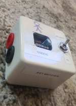
Vero JFET matcher
- Thread starter Stickman393
- Start date
Stickman393
Well-known member
It's like...half signature, half self-portrait.
It's a long story, not dissimilar in its elements from a Chuck Palahniuk novel. It's rife with corporate Kool aid, an ex girlfriend who fancied herself a tattoo artist, and a lonely young man who didn't know much who turned into a slightly older, slightly less lonely man who still doesn't know much.
But yeah, Stickman is me. And other folks, too. We're Stick people, living in a Stick world. You could say that we're Stick in the head, but that's not entirely right. We're Stick in the arms legs and body...really...
And truthfully, would that be so bad? After all, it is no sign of mental health to be well adjusted in a profoundly stick society.
Yup...it's...it's pretty absurd.
Feral Feline
Well-known member
The sticker shock from the price paid to gain knowledge is indeed unsettling, considering the overall low ROI.
I like how you took it on, are a stickler at OWNing it, and still sticking it to The Man.
Stick with it, 393.
I like how you took it on, are a stickler at OWNing it, and still sticking it to The Man.
Stick with it, 393.
peccary
Well-known member
Wild guess: A Banana test jack, panel mount, with solder lug.

No need to be vulgar.
IPv6Freely
Active member
What's it dooooo?
Feral Feline
Well-known member
It verifies the handshakes of the Secret Order of the JFET at the meetings, makes sure there are no interlopers trying to infiltrate the meetings...
Why do you ask? Are you an INTERLOPER?
There are ways of making you talk...
Bring forth the Burning-Tantalum Incense !
Why do you ask? Are you an INTERLOPER?
There are ways of making you talk...
Bring forth the Burning-Tantalum Incense !
IPv6Freely
Active member
But what does it actually do?It verifies the handshakes of the Secret Order of the JFET at the meetings, makes sure there are no interlopers trying to infiltrate the meetings...
Why do you ask? Are you an INTERLOPER?
There are ways of making you talk...
Bring forth the Burning-Tantalum Incense !
IPv6Freely
Active member
Okay I got it. I also built it... but the output is confusing. I don't get the "x10" part.
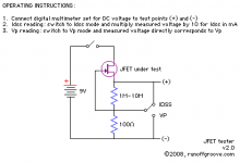
My DMM read 27.7mV for Idss. The instructions (and the sticker on yours) says x10 for mA. But... ohms law says to get mA I should be dividing by 100 (the 100ohm resistor) which gives me 0.27mA for a J201 which is correct. So where is the x10 coming into play?
My DMM read 27.7mV for Idss. The instructions (and the sticker on yours) says x10 for mA. But... ohms law says to get mA I should be dividing by 100 (the 100ohm resistor) which gives me 0.27mA for a J201 which is correct. So where is the x10 coming into play?
Stickman393
Well-known member
It's pretty good at checking for voltage in a 460Vdc panel if you chuck it at exposed terminals.But what does it actually do?
But...something about measuring the on and off voltages for Jfets. Something about current too. Honestly, it's above my head at the moment, but that's part of why I built this thing. Gots to learns n things.
Not sure about the x10 bit. Here's the schematic. Brain still waking up...

IPv6Freely
Active member
Oh, somebody on Discord figured it out. It's assuming you don't have an auto-ranging multimeter, which means its measuring V, not mV like mine was. So much more sense now.It's pretty good at checking for voltage in a 460Vdc panel if you chuck it at exposed terminals.
But...something about measuring the on and off voltages for Jfets. Something about current too. Honestly, it's above my head at the moment, but that's part of why I built this thing. Gots to learns n things.
Not sure about the x10 bit. Here's the schematic. Brain still waking up...
View attachment 14241
Feral Feline
Well-known member
Kinda like how some octave-up fuzz effects need closely matched diodes,But what does it actually do?
some effect-circuit builds require closely-matched JFETs, such as some phaser circuits for example.
Several component vendors offer pre-matched JFETs, usually in twos and fours — I've got a project that requires six.
Matching JFETs is time-consuming, thus you pay a premium for vendors' pre-matched sets, but you might still not get the ideal IDSS or Vp specific range you want, despite getting an expertly well-matched set.
Bulk ordering JFETs and then putting together matched sets yourself...
1) Saves yer dosh (opportunity cost is time)
2) Edjumicates you (opportunity cost: possible inaccurate matching as you learn the ropes)
3) Da Dah, Da da DUHHH Satisfaction! of DIYourselfing (opportunity cost: vendor goes under after spending too much on expensive accurate JFET-measuring machines only to have DIYers doing it for themselves like a buncha sistahs... and thus another source of JFETs dries up. MAYBE)
IPv6Freely
Active member
Interesting about matching JFETS. I didn't know that was a thing. I built this and just used it to test that the J201s I bought from eBay were actually J201s and were in-spec. lolKinda like how some octave-up fuzz effects need closely matched diodes,
some effect-circuit builds require closely-matched JFETs, such as some phaser circuits for example.
Several component vendors offer pre-matched JFETs, usually in twos and fours — I've got a project that requires six.
Matching JFETs is time-consuming, thus you pay a premium for vendors' pre-matched sets, but you might still not get the ideal IDSS or Vp specific range you want, despite getting an expertly well-matched set.
Bulk ordering JFETs and then putting together matched sets yourself...
1) Saves yer dosh (opportunity cost is time)
2) Edjumicates you (opportunity cost: possible inaccurate matching as you learn the ropes)
3) Da Dah, Da da DUHHH Satisfaction! of DIYourselfing (opportunity cost: vendor goes under after spending too much on expensive accurate JFET-measuring machines only to have DIYers doing it for themselves like a buncha sistahs... and thus another source of JFETs dries up. MAYBE)
Stickman393
Well-known member
Just as an FYI:
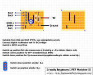
The Vero layout mentions using a 3 position on/off/on sp3t switch.
But...just look at the schematic. That "off" position doesn't do what the layout claims. You'll want to add another spdt on-off switch for that purpose, or swap the sp3t On/off/on for a DP3T on/off/on. Use the second pole to break 9v in the center position.
Feral Feline
Well-known member
@Stickman393 Have you updated your matcher, were you able to squeeze in a DP3T? Gutshot?
Stickman393
Well-known member
Haven't yet, but the idea is simple enough. On the second pole the center common terminal connects to Vero +9vdc in. The top and bottom terminals are jumped out and connected to the DC jack barrel.
That way either up or down position provides a path from the barrel of the 9vdc jack to +9vdc in, but since the center "off" position leaves the common terminal disconnected, the center position effectively breaks the power supply circuit.
Idk, this picture refers to a three position on/off/on single pole switch as a SPDT. Personally, I would consider that "off" position to be a throw as well...making it a SP3T. Although it's true that a SPST consists of an on and off position and is explicitly "single throw....I have no idea what the actual correct terminology is here considering that we have the on/on/on and the on/off/on varieties to contend with.
Brain vomit, away!
Feral Feline
Well-known member
I wasn't considering the nomenclature before, I just used the same "DP3T" to post my question, but now that you bring it up...
Giving it some gray-matter synapse (mis)firings, I'll suggest that a switch that has on-off-on is still only a dual throw, if you look at it as "off" being like "neutral" when driving stick.
Whether it's three-in-the-tree (anybody still drive that?) or four-on-the-floor (again, anybody still drive that? Mostly 5-speeds nowadays if not auto-paddles), you've got neutral; so I guess "on-on-on" is more like the auto-paddle shift.


