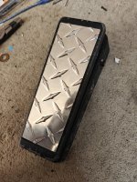
Vintage Cry-Baby

Chuck D. Bones

Circuit Wizard
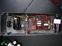
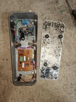
This was built in 1977 in The Valley (Oh my Gawd!). Looks to be all original. Board was wave soldered and there are no signs of repair or modifications.
Battery power only.
Not true bypass.
No reverse voltage protection diode, although the circuit itself is pretty-much immune.
No power supply filtering.
Film caps & one tantalum.
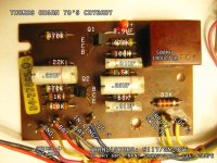
10% tolerance 1/2W carbon comp resistors, except for one 470K 5% carbon film. Some CC resistors have drifted out of spec.
Two transistors marked 5117. Pinout is E-C-B.
Stack of Dimes inductor. DC resistance measures 45Ω.

Thomas 1977 Cry-Baby 02.jpg

Anyone interesting in designing a replacement PCB? Dual-sided, thru plated, same footprint and layout. There are some on the market, but they sell for $32 or higher.
 
This was built in 1977 in The Valley (Oh my Gawd!). Looks to be all original. Board was wave soldered and there are no signs of repair or modifications.
Battery power only.
Not true bypass.
No reverse voltage protection diode, although the circuit itself is pretty-much immune.
No power supply filtering.
Film caps & one tantalum.
10% tolerance 1/2W carbon comp resistors, except for one 470K 5% carbon film. Some CC resistors have drifted out of spec.
Two transistors marked 5117. Pinout is E-C-B.
Stack of Dimes inductor. DC resistance measures 45Ω.
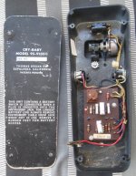
View attachment 121924

Anyone interesting in designing a replacement PCB? Dual-sided, thru plated, same footprint and layout. There are some on the market, but they sell for $32 or higher.
Immune to reverse voltage how? Did you measure the resistors in circuit or did you take them out to measure?
 
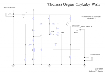
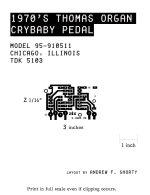
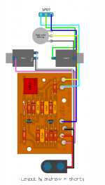
These might be of some help here. I think I found these on FSB many years ago.
 

Attachments

  • wahosg1.jpg
    wahosg1.jpg
    87.3 KB · Views: 18
  • ThomasOrganCrybabySchematic.png
    ThomasOrganCrybabySchematic.png
    144.8 KB · Views: 15
  • ThomasOrganCrybabyPCBLayoutFinal.png
    ThomasOrganCrybabyPCBLayoutFinal.png
    260 KB · Views: 16
  • Crybabypartslayout.jpg
    Crybabypartslayout.jpg
    120.2 KB · Views: 15
  • 70scrybabylayout.png
    70scrybabylayout.png
    232.4 KB · Views: 16
Are you looking for a modern repro of this exact board to be made?
Yes. It would need a universal inductor footprint. I was reluctant to mod a vintage pedal, but the owner got it on the cheap, plans on keeping it and gave me the go-ahead. He's basically looking for more sweep range and higher Q, both of which are easily attained with a few resistor changes.

If I had a drop-in replacement board, then the vintage board could be removed, sold off and replaced with a new one.
 
Last edited:
Boy howdy, I've seen a ton of those boards over the last few years.

I could easily do one in kicad. Certainly got enough examples on hand:

1000058662.jpg

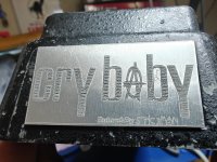
I've read that the 5117's are just rebranded 2n2925s. What's cool is that your example there has the sepulveda, CA backplate, the old TO-98 transistor package, *and* the stack of dimes inductor.

Which follows well with the 1977 date. The vast majority I've seen from that time period have the TDK boxed inductor (which, honestly, IMHO, is unfairly maligned due to a handful of latter day units that fucked with the formula). But...they were known to swap out the inductors at random depending on supply. Chicago-made variants with the stack o dimes are far more common, but by that time they had switched to the TO-92 transistors.

Something I appreciate about these older models is the amount of give a fuck that went into em. The wire-wrap posts, the waxed cord wrapped wire harness.

Anywho, this looks pretty spot on for the era. TO would tend to use whatever they had on hand, the single carbon film 470K isn't unusual. ITW poly film caps, that tant tends to be 3.9uF on these examples from the late 70s.

I'm curious: that one got the Centralab or the Allen Bradley pot?
 
Just a Thomas Organ internal part number. Like I said, 2N2925s are the word on the street.

The earliest dunlop crybabys have 'em too. The TO-92 variant, at least. Leftovers from the TO buyout.

I've got a few examples like that. Including this one:

1000058975.jpg

1000058978.jpg
1000058979.jpg

Little transitional circuit board right there. Dunlop was getting fancy with the quick connect plugs after they ran out of TO boards. But they were using greenies and carbon film resistors, and the 4.7uF bypass cap was electrolytic and not at all a soaked-in-blood combat mineral. Which I cannot stand for.

So, ya know. Choppa choppa.
 
I'm curious: that one got the Centralab or the Allen Bradley pot?
I can't see any mfgr name or logo on the pot body and don't feel like disturbing it by removing it. Any other way to tell the diff?

These days, AVX & KEMET obtain their tantalum from vetted non-conflict sources. IMHO, tantalum is superior in this application. It may look like a bypass cap, but it is in fact an integral part of the audio path.

Is that a range switch hidden under the treadle?

It makes no sense to me to stamp the serial # on the bottom plate when it is so easy to swap bottom plates between units.
 
I can't see any mfgr name or logo on the pot body and don't feel like disturbing it by removing it. Any other way to tell the diff?

If that's the case I'd venture an educated guess that it's the centralab.

Dunno why the change happened, but centralabs have lot/identifying numbers around the outer edge of the back of the potentiometer. AB'S are a bit more loud In their branding.

It makes no sense to me to stamp the serial # on the bottom plate when it is so easy to swap bottom plates between units.

Truthfully? Aside from this fact, them bottom plates are garbage for discerning date of manufacture. There's a website that claims you can infer the date by adding 57 to the first two numbers.

That isn't true. I've documented every crybaby that's passed through my hands here.

The potentiometer date code is a much more reliable way to determine approximate date of manufacture: so long as it's original, at least. Which can be a problem.

What I have noticed is that the serial numbers are sequential (I mean, like, the SNs increase over time) regardless of if it's a TO or a dunlop. So that document I linked to can getcha in a ballpark, though I do have some holes in the timeline.

These days, AVX & KEMET obtain their tantalum from vetted non-conflict sources. IMHO, tantalum is superior in this application. It may look like a bypass cap, but it is in fact an integral part of the audio path.

Cards on the table: there's a lot I don't understand about how everything in the circuit interacts. I gotta admit from my own experimentation that I have an affinity for tants in this position.

Which...is ethically dicey. I typically use vintage NOS stuffs in my builds. Cause then, at least the suffering is aged. Like wine. Toan is in the crimes against humanity.

In all honesty: even the non-conflict sourced stuff is...ah...well. Call me a skeptic. I mean, sure, I appreciate the efforts towards "ethical" sourcing, but...

Eh. I have thoughts. I'll save this thread from them.

Is that a range switch hidden under the treadle?

Don't trust side-mounted controls. Plus, it's like a knife in a shoe. Bend over and....whaaat!?!? Is that toan slightly fatter?!?!?!?

@Stickman393 - Actual guitarist? ✅

Honestly, I'm more into chasing Stickwife around with these in hand, rocking them back and forth, and making the "wah wah wah" sound with my mouth.

No matter how much she asks me to stop.
 
Last edited:
Anyone interesting in designing a replacement PCB? Dual-sided, thru plated, same footprint and layout.

I could take a crack. It looks pretty straightforward. I'd want to have accurate measurements of everything though.
Specifically, the PCB dimensions and more importantly, the offsets of the mounting/screwholes. (Though I can probably
get some fairly good estimates from the post by @chordball)

I'd probably also make most of the footprints dual-mount - e.g. holes for either the giant mica(?) cap or a modern
box film cap, holes for 1/4 watt resistors as well as the big carbon comps, etc.

For the inductor footprint, I'd probably need to see some of the pinouts/measurements of the inductors that are
floating around, if they're different sized than the one in the above layout. There's also the stompbox
parts wah-me-6.
 
Back
Top