You are using an out of date browser. It may not display this or other websites correctly.
You should upgrade or use an alternative browser.
You should upgrade or use an alternative browser.
What’s on *YOUR* workbench?
- Thread starter Bricksnbeatles
- Start date

almondcity
Well-known member
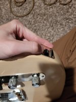
Can anyone explain why I shouldn't replace the standard tele jack with this curved jack plate? I'll have to take the old one off to see how flush it gets with the body but if it fits well enough I may go for it. Otherwise I also got an electrosocket
Attachments
andare
Well-known member
If you can guess what this is you're a total nerd. Well done!

For the rest of us, it's a Tone Bender Mk1. I'm not done yet as I learn more about these circuits and try to emulate the tone of the originals and the official modern recreations but I'm also starting to feel out what this circuit sounds with my rig and I'm trying to tailor it to my preferences.
Tweaks that worked:
Swapping transistors with different hFE and Iceo didn’t fix the sound with Q3c above -8.5V.
Lowering the 2.2M resistor to 1M made it a tad louder but it ruined the decay of the notes. 2.2M can go above unity if Attack is high enough. I need to see what happens if I get rid of R9 (47k).
Q1
Not much noisy at all. Unity is at 2-3 o'clock with very little change up from there.
Today I'm going to try different transistors to see if I can get it to gate across more of the Attack sweep. At this point I'm not so concerned with it sounding true to the originals because they all sound different. The recent ones from Sola Sound all sound pretty similar, however mine sounds cooler to me")
Any suggestions and tips are welcome!

For the rest of us, it's a Tone Bender Mk1. I'm not done yet as I learn more about these circuits and try to emulate the tone of the originals and the official modern recreations but I'm also starting to feel out what this circuit sounds with my rig and I'm trying to tailor it to my preferences.
Tweaks that worked:
- R3 to 330k. 470k has a lot of gated tones, 180k very few. The lower the value the higher the gain. Doh! for you, a realization for me. 330k is a happy medium.
- R7 to 120k to lower Q3c below -8.5V. Upping it to 200k brings it closer to -8V. Can't really tell the difference.
- Attack pot A50k. B50k had almost no sound at 0 and a sudden increase in gain at 9 o’clock. The log pot has sound at 0 and a more gradual gating range at the beginning of the sweep. Big improvement in usability.
Swapping transistors with different hFE and Iceo didn’t fix the sound with Q3c above -8.5V.
Lowering the 2.2M resistor to 1M made it a tad louder but it ruined the decay of the notes. 2.2M can go above unity if Attack is high enough. I need to see what happens if I get rid of R9 (47k).
Q1
- #002 in my stash
- AC125
- hFE 86
- Iceo 202uA
- #029 in my stash
- ASY34S
- hFE 117
- Iceo 43uA
- #031 in my stash
- ASY34S
- hFE 490 - Huh? Very suspicious...
- Iceo 133uA
- Q1e -1.25V
- Q1b -1.3V
- Q1c -9.14V
- Q2e 0
- Q2b -0.05V
- Q2c -9.11V
- Q3e 0
- Q3b 0
- Q3c -8.60V
- Q1e -1.26V
- Q1b -1.3V
- Q1c -9V
- Q2e 0
- Q2b -0.19V
- Q2c -4.61V
- Q3e 0
- Q3b -0.01V
- Q3c -8.34V
Not much noisy at all. Unity is at 2-3 o'clock with very little change up from there.
Today I'm going to try different transistors to see if I can get it to gate across more of the Attack sweep. At this point I'm not so concerned with it sounding true to the originals because they all sound different. The recent ones from Sola Sound all sound pretty similar, however mine sounds cooler to me
Any suggestions and tips are welcome!
andare
Well-known member
Today I breadboarded a Germanium fuzz face. I got low leakage trannies around 70 and 120 so it biased to -0.7V and -4.5V with the stock values.
Plug it in and it sounds crazy.
The cleanup is fantastic. Super bright.
Sunfaces got nothing on it.
However it splats my amp, it sags and sputters, especially in 4th position with my Strat.
My Dunlop FFs (JDF2 and JHF1) don't do that. Is it just a matter or lowering the gain or should I bias Q2 higher?
Harry Klippton
Not Interested
Are you playing it into a clean amp?Today I breadboarded a Germanium fuzz face. I got low leakage trannies around 70 and 120 so it biased to -0.7V and -4.5V with the stock values.
Plug it in and it sounds crazy.
The cleanup is fantastic. Super bright.
Sunfaces got nothing on it.
However it splats my amp, it sags and sputters, especially in 4th position with my Strat.
My Dunlop FFs (JDF2 and JHF1) don't do that. Is it just a matter or lowering the gain or should I bias Q2 higher?
andare
Well-known member
No, I'm playing into a dirty tube amp, a bit of breakup w/Strat volume on 10.Are you playing it into a clean amp?
I just tried it into a Rumble - a clean SS bass amp - and it doesn't splat.
BTW to be precise I built a Tone Bender 1.5, not a Fuzz Face. Practically the same, I know, but just to be exact: 4u7 input cap, 47k on Q1c, 25u emitter cap and A100k volume pot.
Q1 hFE 79, leakage 26uA
Q1 hFE 122, leakage 57uA

Bricksnbeatles
Member known well
Is that the new Chromium powder coat?
andare
Well-known member
Ge Fuzzrite. Stock. I've added resistors across the pots to get the classic values but can't tell the difference without.

Q1 hFE 79, Q2 hFE 39
I've tried both at 90, both at 30, Q1 at >200 and Q2 at 50 etc. Gain varies but the background hiss just won't be tamed.
10n cap from input to ground helps get rid of weird noises but that's it.
This is a fuzz that must be played into a clean or cleanish tube amp otherwise mayhem ensues. This also keeps it very bright and the volume varies across the sweep of the Depth knob.
If I push my amp into light breakup, it gets darker and compressed. So much so that taking out the 22k high pass filter doesn't even register.
On to the Rush Pep Box.
swyse
Well-known member
I saw your post there and was wondering how the build went and then saw your post was so recent. I'm really curious about how close this simplified circuit can get to the real deal.Found it on FSB. A klon style od with no buffer or charge pump. Should be interesting.
andare
Well-known member
Germanium Rush Pep Box.
Q1 80, Q2 59
I like the gated tone, I don't like how noisy it is. A lot of Germanium sizzle. Sounds like bacon in a cast iron skillet but it tastes rather metallic. Too bad because it cleans up well. Maybe different transistors would help but I ain't got 'em. It's dark as well.

I think my Tone bender Mk1 is done. I need to put together a turret board diagram and order the mojo parts. It's a thing of beauty.
I also went back to yesterday's TB Mk1.5. I lowered the gain on my amp and now it doesn't sag anymore. I fully believe the Germanium hype now. With the right amp settings and Attack at 10, this thing goes from obese fuzz (with that crumbliness that I'd only heard in demos of original units and Sunfaces) to "glassy cleans" that sound like chorus. And I didn't have to sell a kidney and half my pancreas to buy NKT275s.
It really is a magical circuit.
I also have a TB Mk2 on another breadboard that needs tweaking because right now it's a bit underwhelming.
Yes, I've been breadboarding exclusively because I'm broke
steviejr92
Authorized Vendor

Seabed Delay.
This one’s for my Dad he’s done nothing but support me my whole life I think it’s only right I repay him.
Just finished up the board. And drilled the enclosure. Just waiting on jacks to come in to finish up!
andare
Well-known member
That's just beautiful. I wish my dad played guitar.View attachment 33251
Seabed Delay.
This one’s for my Dad he’s done nothing but support me my whole life I think it’s only right I repay him.
Just finished up the board. And drilled the enclosure. Just waiting on jacks to come in to finish up!
steviejr92
Authorized Vendor
He doesnt play as much as i do he just owns an electric acoustic. He doesnt know anything about pedals or effects haha i hope this will open his eyes on this hobby. It should play very nice with his acoustic though.That's just beautiful. I wish my dad played guitar.
andare
Well-known member
Before I build my Ge Tone Benders (on turret board) I'm trying to wrap my heard around pedal power with battery, power supply and a voltage inverter.
Is this correct? The LED is missing but the anode would go to + on the DC jack and it would be connected to ground by the 3PDT footswitch of course. The 1N5817 for polarity protection is also missing. I'll have to add it to the voltage inverter board.

Is this correct? The LED is missing but the anode would go to + on the DC jack and it would be connected to ground by the 3PDT footswitch of course. The 1N5817 for polarity protection is also missing. I'll have to add it to the voltage inverter board.

Last edited:
benny_profane
Well-known member
Connect the battery negative terminal to the ring of the input jack. Remove the connection between the ring and the DC jack and connect it to the sleeve instead. You want the battery to only be shorted when a cable is inserted into the input. Otherwise, I think it looks good.Before I build my Ge Tone Benders (on turret board) I'm trying to wrap my heard around pedal power with battery, power supply and a voltage inverter.
Is this correct? The LED is missing but the anode would go to + on the DC jack and it would be connected to ground by the 3PDT footswitch of course. The 1N5817 for polarity protection is also missing. I'll have to add it to the voltage inverter board.
EDIT: This would require a bit more to work. Go with the first suggestion.
Last edited:
andare
Well-known member
Connect the battery negative terminal to the ring of the input jack. Remove the connection between the ring and the DC jack and connect it to the sleeve instead. You want the battery to only be shorted when a cable is inserted into the input. Otherwise, I think it looks good.
Like this?

Since the DC jack is switching, you could also bypass the voltage inverter board for the battery and arrange it as positive ground. The same principle of using the ring to switch the ground would apply.
I can't figure out how to do that...
Ctrl4Smilerz
Well-known member

Got the frame for my new pedalboard glued.
benny_profane
Well-known member
On second thought, just do it as you have it. You'll run into problems with the LED and would probably need to run some diodes as well. The wiring diagram you posted is correct.I can't figure out how to do that...
szukalski
Well-known member
Right? It’s a pain to tweak but there’s something special when you get it right. That’s why you breadboard these ones.I fully believe the Germanium hype now.
I really enjoy all the Mks.