You are using an out of date browser. It may not display this or other websites correctly.
You should upgrade or use an alternative browser.
You should upgrade or use an alternative browser.
Missing Build Docs / Schematics
- Thread starter Robert
- Start date
Robert
Reverse Engineer
Hey Robert, do you have the drill template for the new "Handy Expression Controllers"?
This template assumes you are using a long pin 16mm pot. The PCB should be oriented with the PedalPCB logo facing you when looking inside the back of the enclosure.
And the passive splitter as well, just in case:
For the splitter it's easiest if you mount the jacks in the enclosure first, then drop the PCB on top and solder in place.
You might want to grab an extra washer for the jacks to get the best fit.

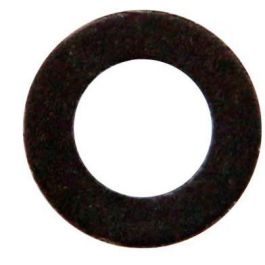
Black Washer for 6.35mm 1/4" Socket
Tayda Electronics - Get It Fast - Same Day Shipping
nate433
Active member
Thanks Robert!
This template assumes you are using a long pin 16mm pot. The PCB should be oriented with the PedalPCB logo facing you when looking inside the back of the enclosure.
And the passive splitter as well, just in case:
For the splitter it's easiest if you mount the jacks in the enclosure first, then drop the PCB on top and solder in place.
You might want to grab an extra washer for the jacks to get the best fit.

Black Washer for 6.35mm 1/4" Socket
Tayda Electronics - Get It Fast - Same Day Shippingwww.taydaelectronics.com
PangeaDestructor
Active member
What color are the Lycan clipping diodes?
Robert
Reverse Engineer
Idk if the new ADHD is on the list/requested, but I put all the PCBs together a month ago and don’t want to screw up when drilling the enclosure. Thanks in advance!
Robert
Reverse Engineer
Could I get a drill template for the Deofol? Or could someone point me to something with the same layout?
Thank you very much!!
Robert
Reverse Engineer
Any docs for the Basic Relay DPDT Switch (Latching) please?
It's really not much different from the Latching Basic Relay Bypass Module, it just exposes all six contacts of the relay rather than being bound to a true-bypass configuration.
Just keep in mind the Latching version powers up with contacts A1/A2 and B1/B2 closed, the Non-Latching version powers up with contacts A2/A3 and B2/B3 closed.
Also, there is no onboard polarity protection so you'll want to tap power from a node that is already protected from reverse polarity, or make the VCC connection with an offboard diode in-line. (I do plan to change this at some point in the future)
benny_profane
Well-known member
Echoing my request for a protected courtesy Vcc out on the boards.Also, there is no onboard polarity protection so you'll want to tap power from a node that is already protected from reverse polarity, or make the VCC connection with an offboard diode in-line. (I do plan to change this at some point in the future)
Robert
Reverse Engineer
There already is one, right here.Echoing my request for a protected courtesy Vcc out on the boards.

Seriously though, I do like the idea but I'd only want to do it if it could be uniform across all of the projects and that might be a little tricky on some of the dense layouts.
I've considered another version of the DC jack breakout board to include polarity protection and additional filtering, that might be the best way to handle something like that.
caspercody
Active member
Having issues with my Bobby build, is there a schematic, and PCB layout? Need it to figure out my build
Robert
Reverse Engineer
Having issues with my Bobby build, is there a schematic, and PCB layout? Need it to figure out my build
caspercody
Active member
Thank you!!!
caspercody
Active member
Got it fixed, another bad pot. Works now, thanks!!!
Anyway to see the schematic for the Doxie?
Anyway to see the schematic for the Doxie?
Morbidpale
Well-known member
Any chance there is a schematic available for the double Jeopardy boost?
