What’s on *YOUR* workbench?

I was mostly curious about the lower limit so it doesn't burn out prematurely? Normally I wouldn't care too much, but like I said, they're dimmer than most LED's to begin with. Or am I worrying too much?
I've used UV LEDs a couple of times, and as I recall it I went below 2K with no problems. Possibly as low as 1K. I'd have to open pedals and check to be sure.

There are LED resistor calculators online - Googling that phrase will find you some. For our purposes the numbers needn't be exact, the point is that most LEDs will work at much lower resistances than we'd typically use, they'd just be way too bright. Personally I find 4.7K too bright for most uses and typically use anything from 5.6 to 15K. I test LEDs to see what looks acceptable to me.

UV LEDs are not bright, though. So lower resistance makes them usable for humans. It is possible that they're pumping out invisible-to-humans UV light which is potentially harmful. As in, it can harm your eyes even if you can't see it. I doubt there's much chance the UV will harm your skin any more than a sunny day, but hey, people die of melanomas on a regular basis here in Australia. So I'm a bit wary of using UV LEDs and I wish someone would just make a white LED with a dark purple plastic lens, so we could have genuinely purple LEDs without potentially scarring our retinas.
 
Last edited:
I've used UV LEDs a couple of times, and as I recall it I went below 2K with no problems. Possibly as low as 1K. I'd have to open pedals and check to be sure.

There are LED resistor calculators online - Googling that phrase will find you some. For our purposes the numbers needn't be exact, the point is that most LEDs will work at much lower resistances than we'd typically use, they'd just be way too bright. Personally I find 4.7K too bright for most uses and typically use anything from 5.6 to 15K. I test LEDs to see what looks acceptable to me.

UV LEDs are not bright, though. So lower resistance makes them usable for humans. It is possible that they're pumping out invisible-to-humans UV light which is potentially harmful. As in, it can harm your eyes even if you can't see it. I doubt there's much chance the UV will harm your skin any more than a sunny day, but hey, people die of melanomas on a regular basis here in Australia. So I'm a bit wary of using UV LEDs and I wish someone would just make a white LED with a dark purple plastic lens, so we could have genuinely purple LEDs without potentially scarring our retinas.
That's a fair point. I did a bunch of digging (keep in mind, I'm not an expert and this is just simple googling based on potentially unreliable sources - although these people sure seem like they know what they're talking about):

Top answer here https://electronics.stackexchange.com/questions/123674/are-uv-leds-really-dangerous gives us some guidelines on the maximum safe power, and seems quite cautious in general. So anything over 5mW should be used with eye protection. Using the Tayda UV led in a calculator, at full 20mA the resistor is 275 ohms and output is 0.11W, so 110mW. That's possibly something you should avoid, even though there are other parameters in play which means it's not just 22 times over the safe threshold, mainly that the Tayda LED is actually 410-415nm which isn't actually in the UV range, it's more of blue, but since it's not just a single frequency it's emitting, it's also emitting some UV light - but most of the power will be used for blue visible light.

5mA would mean a 1100 ohm resistor, and 27.5mW. 5mW would mean something like a 6k ohm resistor, so if you want to be absolutely safe, it's best to avoid them completely.

If you're not so easily scared, here's a longer reply from someone who seems to have studied it a bunch due to causing their wife to burn their eyes with an UV lamp https://electronics.stackexchange.com/questions/25851/safety-guidelines-for-ultraviolet-leds

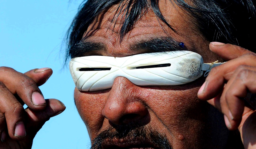
But the tl;dr is that UV light damage in eyes is basically "snowblindness", as in your eyes get sore and inflammated, which could lead to temporary blindness due to your eyes literally swelling shut. But probably no permanent damage, unless it was much more powerful or focused than the light that causes snowblindness. So it's pretty reasonable to assume that a LED that mostly doesn't emit UV light anyway (and then there are UV-A, UV-B and UV-C - UV-C is more scary, but again the LED barely gets into UV-A territory which is considered pretty harmless) and emits that rather weakly, plus whatever the diffusion caused by sanding causes, that using them in pedal lights is safe. UV light is also considered harmful because it doesn't cause a blink reflex since you can't see it, but again, if you're emitting visible light, you're probably hitting the blink reflex first before the UV is strong enough to do even any damage.
 
@Fama - here's the Crankshaft pedal I made, featuring a UV LED from AliExpress. I bought a few different types of UV LED trying to find something that I liked, and these were the best. They're quite purpley in real life but look blue in photos. I used a 2K resistor for this one, it's not that bright but still pretty visible.

EDIT: Build report here.

EDIT 2: Build report for the Special K, also using a UV Led, with a 1K resistor.

EDIT 3: Added a pic of the Special K in low light, trying to show the purpleness, which actually worked pretty well.
 

Attachments

  • cra.jpg
    cra.jpg
    249.3 KB · Views: 7
  • SPK.jpg
    SPK.jpg
    193.6 KB · Views: 7
Last edited:
Snow-Goggles-Inuit.jpg
 
Of all the flangers I've built, I think I found one I actually like
1000013488.jpg

Still need to fine tune the Manual trimpots, but this one sounds pretty rad as is. The range of all the pots is almost staggering, but it sounds great throughout.

Considering putting the Phase toggle on a stomp switch and breaking the LFO bias trimpot out for an external pot
 
Finally, I got some unobtainable OPA205 op amps. They've been on my radar for a couple of years. They're still considered prototypes (XOPA205) and you can only get them straight from TI. What's so special about them? Well, they have the best tradeoff between power and noise of any audio IC that I have found from any manufacturer at any price, while being suitable to use with high impedance sources (i.e. guitar pickups). 0.22mA of quiescent current gets you about 7nV/sqrt(Hz) of noise, which is the equivalent of a single 3k resistor followed by an ideal op amp. Best guitar/bass active buffer (or booster) ever!

1687911652412.jpeg
 
You live in Florida yeah? That looks unbearably hot
Yes im in Florida! Dude its incredibly hot in there. You could feel it just as I was closing up the last roofing piece. Then as i was putting on the plastic covers for the screws I really felt it, its gets blazing hot in there! Luckily I thought ahead for that. I'm insulating the shed and getting an AC unit that has a dehumidifier in there as well. Its rated for a large room, so hopefully I shouldn't be dying in there while working! :ROFLMAO:
 
Yes im in Florida! Dude its incredibly hot in there. You could feel it just as I was closing up the last roofing piece. Then as i was putting on the plastic covers for the screws I really felt it, its gets blazing hot in there! Luckily I thought ahead for that. I'm insulating the shed and getting an AC unit that has a dehumidifier in there as well. Its rated for a large room, so hopefully I shouldn't be dying in there while working! :ROFLMAO:
Any chance of insulation to help protect stuff when the AC isn't on?
 
Picked up this non-functioning Double Tracker off reverb for $50. Looks like there are a couple of switches that could be added? Anyone know about switch 3 and the empty bottom area by chance?

IMG_8059.jpeg
 
Picked up this non-functioning Double Tracker off reverb for $50. Looks like there are a couple of switches that could be added? Anyone know about switch 3 and the empty bottom area by chance?

View attachment 51321
They use the same board for most of their fv-1 effects. Since sw3 is for trails, it only really makes sense for reverb and longer delays, so no use in including it on the double tracker
 
IMG_7809.jpeg
Some troubleshooting to do later tonight. Got the electros swapped for SMDs, then wired it all up. Initially when I plugged it in, the volume, bass, and midrange controls were working, but the gain and tone pots did nothing. Then as I was testing the midrange control, the led suddenly shut off (though it was still passing sound) and when I took a look back inside, I found that the CLR was reading 0 Ω— realized that the metal support tab on the pot was shorting the power-side of the CLR to ground, which was shorting the entire power supply to ground— odd that it didn’t cut the sound out entirely when that happened. Anyway, I bent that tab away from the PCB, measured for Continuity and found that everything seemed to be in order with no other shorts and tested it again, but still no light. Had to run out before I could test anything out, but hopefully it’s a quick diagnosis. Also have to check the power supply out to make sure that didn’t blow itself from being briefly shorted out
 
View attachment 51346
Some troubleshooting to do later tonight. Got the electros swapped for SMDs, then wired it all up. Initially when I plugged it in, the volume, bass, and midrange controls were working, but the gain and tone pots did nothing. Then as I was testing the midrange control, the led suddenly shut off (though it was still passing sound) and when I took a look back inside, I found that the CLR was reading 0 Ω— realized that the metal support tab on the pot was shorting the power-side of the CLR to ground, which was shorting the entire power supply to ground— odd that it didn’t cut the sound out entirely when that happened. Anyway, I bent that tab away from the PCB, measured for Continuity and found that everything seemed to be in order with no other shorts and tested it again, but still no light. Had to run out before I could test anything out, but hopefully it’s a quick diagnosis. Also have to check the power supply out to make sure that didn’t blow itself from being briefly shorted out
Check the LED with your DMM, it should light up in continuity mode.
 
Check the LED with your DMM, it should light up in continuity mode.
For whatever reason my DMM absolutely never works for testing LEDs, so I just use my cheap transistor tester.

Anyway, checked the power supply and it’s all good. Measured the voltages on the IC while I was at it, and they’re all where they should be. CLR measures good, so that’s good. TC-1 reads the led as a 7pf cap when in bypass and a 40pf cap when the switch is engaged, rather than a diode now, so that’s clearly messed up, though why, I’m not sure— if the CLR is still reading good (4k7 in this case) and the power shorted to ground, rather than across the CLR, then there’s no point in time where it would’ve been “exposed” to “danger.”

Similarly odd, the gain pot measures correctly— 910k (1M - ~10% tolerance) at full cw, and 9k8 at full ccw; continuity where it should be, and none where it shouldn’t be, so it *should* be altering the gain of the first op amp stage.
Anyway, I’m just rambling to myself. I’ll do a deeper dive when it’s not late at night.

Edit: gets weirder. Clipped the LED out. Tests as “missing/damaged” in the TC-1. Tested A/K pads where it was, and in bypass it reads 11pF and engaged 690uF. Too tired to make sense of that, since with the multimeter it reads as an open circuit between A/K, while K to Gnd reads as an open circuit when bypsssed, and 0 Ω when engaged, just as it should. A fresh brain should make it easier
 
Last edited:
Back
Top