Dual EEPROMs and internal algo mods (and possibly hilariously offensive content)

Paradox916

Well-known member
Hey kids do you like butt stuff? ACC166A6-CC01-4C95-9DDE-37D8BBF0C580.jpeg
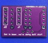
Well maybe not the butt stuff you were looking for but I promise your arachnids EEPROM dip socket will never be the same! As this is just an addendum to what others have done like @JamieJ I wanted to use this to cover a lot of personal ground ( learning diptrace, make a dual EEPROM, mod a FV-1 circuit, and make a dirty joke…ect) but if I was going to publicly engage in jackassery I wanted it to be clean as possible, there was no way I was ever going stick my iron in another dirty strip board! the messy wires, the hogged out holes, lumpy solder, and drippy flux… OH THE SHAME! On top of that I wanted to make this a “a plug N play” mod, With the option of being able to make the switch external with minimal off board wiring… DFCB8794-E2E3-439C-BAF6-A0F40B45B8A3.jpeg
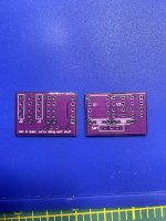
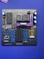
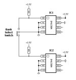
Now this fits snuggly into the arachnid footprint C0AAC7DD-3B31-4EA0-A078-251884E81EEB.jpeg and will sit low enough in a 125b ( but you do have to pay attention to height if you use headers and don’t trim them down as the clearance to the back will be close( you can’t just go jamming it in there!) the idea is pretty simple and here is a schematic for you nerds. 77F864BD-93A6-4863-B61A-D5F6A0EE7649.jpeg
“But what if twin action isn’t that exciting to me and I want a 3 way with my butt stuff?” Say no more
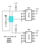
B969309D-A66A-408B-B699-0F4BD90B1230.jpeg

With a DP…. 😮…. Let me finish… with a DPDT on/off/on you can have access to the internal algorithms with a jumper off of R5! Now you have 23 algorithms! If that isn’t enough for you then you seriously need to consider seeking help, you are a dirty little monkey and you are out of control!… and finally I have a few extra of these so if you are in the lower 48 and into butt stuff hit me with a DM!
 
Hey kids do you like butt stuff? View attachment 52747

Well maybe not the butt stuff you were looking for but I promise your arachnids EEPROM dip socket will never be the same! As this is just an addendum to what others have done like @JamieJ I wanted to use this to cover a lot of personal ground ( learning diptrace, make a dual EEPROM, mod a FV-1 circuit, and make a dirty joke…ect) but if I was going to publicly engage in jackassery I wanted it to be clean as possible, there was no way I was ever going stick my iron in another dirty strip board! the messy wires, the hogged out holes, lumpy solder, and drippy flux… OH THE SHAME! On top of that I wanted to make this a “a plug N play” mod, With the option of being able to make the switch external with minimal off board wiring… View attachment 52749
Now this fits snuggly into the arachnid footprint View attachment 52752and will sit low enough in a 125b ( but you do have to pay attention to height if you use headers and don’t trim them down as the clearance to the back will be close( you can’t just go jamming it in there!) the idea is pretty simple and here is a schematic for you nerds.View attachment 52750

“But what if twin action isn’t that exciting to me and I want a 3 way with my butt stuff?” Say no more
View attachment 52751

With a DP…. 😮…. Let me finish… with a DPDT on/off/on you can have access to the internal algorithms with a jumper off of R5! Now you have 23 algorithms! If that isn’t enough for you then you seriously need to consider seeking help, you are a dirty little monkey and you are out of control!… and finally I have a few extra of these so if you are in the lower 48 and into butt stuff hit me with a DM!
Is there enough room in a 125B to put the bank select on a DPDT footswitch?
 
Wow, I was just talking to someone about this. Fantastical work! :love:
It’s not perfect there are some small quirks like the switch pads are a little tight, nothing bigger that 24g will fit, the resistor pads are a little big, and the fv-1 won’t change modes when switching banks untill you turn the mode switch ( maybe pin 7 (wp) needs 3.3v instead of ground for it to switch on the fly, (not sure haven’t dove that far into it yet, but it does work fIne Maybe an issues to tackle next version.
 
  • Like
Reactions: fig
Is there enough room in a 125B to put the bank select on a DPDT footswitch?
maybe if you move the bypass over but I don’t care for 125bs with two stomps so I didn’t really look into it, the main problem with this isn’t the foot switch it’s changing algos in the fly. But I think I might know how to do that, it would require a change to the circuit but not 100% on that yet.
 
Last edited:
Nice and clean! I really dig it!
23 algorithms! If that isn’t enough for you then you seriously need to consider seeking help, you are a dirty little monkey and you are out of control!
I’ve been thinking about making one with a 1p12t and smd eeeproms. 96 algos. Been holding off though because it’s a dumb idea. Now I feel like a silly, dirty, out-of-control, little dirty monkey
IMG_8515.jpeg
 
Nice and clean! I really dig it!

I’ve been thinking about making one with a 1p12t and smd eeeproms. 96 algos. Been holding off though because it’s a dumb idea. Now I feel like a silly, dirty, out-of-control, little dirty monkey
View attachment 52759
at one point I thought about a 4 chip set but this made me realize I don’t know if I can come up with 16 useable ones that I like,
 
  • Like
Reactions: fig
at one point I thought about a 4 chip set but this made me realize I don’t know if I can come up with 16 useable ones that I like,
I do plan on doing one board with 3 eeproms and a 3 color led for indication, but that’ll be a fully integrated PCB and not just a daughterboard (for the sake of less painful offboard wiring)

Blue bank: delay/reverbs green bank: modulation red bank: miscellaneous stuff (mostly ring mod/bitcrushing)
 
I laffed. Then I laff some more b/c I am 12.

Also, I may not have read carefully: do you need to power cycle after switching or just change to another bank? Seems like I tried this at one point but I just can't remember the answer.
 
I laffed. Then I laff some more b/c I am 12.

Also, I may not have read carefully: do you need to power cycle after switching or just change to another bank? Seems like I tried this at one point but I just can't remember the answer.
Just change to a different patch, for clarification say we are on patch 4 of EEPROM 1 (bank1)then switch to EEPROM 2 (bank 2) the active patch is still patch 4 on EEPROM/bank 1 then if you turn the mode knob to patch 3 or 5 then you will be utilizing the patches from bank/EEPROM 2. If that makes sense, I bet there is an easy fix for this and someone has it sorted out… just not me I’m still a noob at this sort of thing.
 
Just change to a different patch, for clarification say we are on patch 4 of EEPROM 1 (bank1)then switch to EEPROM 2 (bank 2) the active patch is still patch 4 on EEPROM/bank 1 then if you turn the mode knob to patch 3 or 5 then you will be utilizing the patches from bank/EEPROM 2. If that makes sense, I bet there is an easy fix for this and someone has it sorted out… just not me I’m still a noob at this sort of thing.

Oh yeah, should have said patch not bank. But, your explanation makes perfect sense thanks.
 
Oh yeah, should have said patch not bank. But, your explanation makes perfect sense thanks.
We both knew exactly what you were saying, I was just trying to word it in a way everyone could hopefully understand what we were talking about. This 💩 can get confusing, I know it does for me.
 
The 3 position switch version should auto load the new program because you briefly toggle pin 13 to signal a program change to the FV-1.

With the 2 position switch the FV-1 has no indication that the EEPROM has changed and that it should re-load a program. So you will have to move 1p8t rotary switch to signal to the FV-1 to re-load its program.
 
Back
Top