1uf Non-Electrolytic - What To Use?

Ginsly

Well-known member
Looking at some layouts, I'm seeing some low uf values represented as non-electrolytic caps (1 uf in a specific case). It's clear they intend for a non-polarized cap to be used there.

-Can I use an electrolytic cap there with no ill effects if I orient it the correct way? It's all I have on hand in that value.

-If not, would an MLCC be ok or should I stick get a box cap/greenie? I realize a higher MLCC wouldn't be C0G, which seems to be preferable for those. It looks like I might have space for either one in this particular layout fwiw.

I was just going to grab an assortment like this to fill a couple low-uf gaps- bad idea? https://www.amazon.com/gp/product/B0C1V8Q93P/ref=ox_sc_act_title_3?smid=A3FX7C4A9P37IQ

This is for a fuzz pedal, and I'm mostly concerned about using anything that might make it even noisier than it needs to be! Maybe this doesn't matter much...
 
Thanks @Brett ! Yep I have good amount of those values in Kemet box caps already, otherwise that assortment looks great. It's way too early to place another Mouser order! Ha...

Based on the layout, a red or green dipped polyester cap is what they expect to be there. Wish there was a decent assortment of those on Amazon that included 1uf...

What are the drawbacks of an MLCC in that 1uf position? It would just be good to know for future reference. I'm clearly just starting out! :)
 
A MLCC may be considered to be less optimal in certain positions compared to polyester, but it should still function.
I guess I'm wondering why it may be less optimal in the higher ranges (like 1uf). Noisier? More prone to failure?

Between box caps and dipped mylar reds/greens, which would you choose? Seems like either would be preferable to a 1uf MLCC, so that's what I'll stick to.

Thanks, I appreciate you chiming in. Every little bit helps all of this make sense. Some say they'll only use polarized elec. caps from 1uf and up, but that's clearly not what's indicated in the layout. I'm not even sure which way I'd orient it!
 
Sure, you can do that, but you'll need (want) a schematic to determine the correct orientation.

Do not be afraid of MLCC, they are not the enemy. 😂
Ha, great to hear Robert! It seems pretty clear that using MLCCs for small pf values is totally fine, but I just wasn't sure if using one for 1uf, maybe 2.2uf was a bad idea for some reason. I've read some things scaring me away from larger, non-C0G MLCCs...
 
@Robert - I similarly can't see any real problem using a 1uf MLCC in the above layout... why might some people have a problem with it? Is there any drawback at all?
 
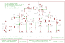
Here's where the 1uf is in the signal path. So it wouldn't really matter sound-wise if I used an MLCC, box, or greenie here? I've read MLCCs can be microphonic, and to avoid them in higher (non C0G values) - untrue?

Also - I don't have any 1N34A germ diodes for D1 & D5. I do have some BAT41 and BAT46 - any chance those would work? Otherwise I could just try silicon I suppose. This schematic oddly has five diodes listed, yet the vero layout posted above only has four...?
samedi-311214.png
Also
 
BAT41 and BAT46 are silicon Schottky diodes. They should work, and will have low forward voltages similar to a germanium diode and may get you most of the way to the germanium diode sound (because different diodes have different I vs V curves, which also contribute to the sound). There are only four diodes in your vero layout becuase they have omitted D4 from the above schematic, which is largely useless.

For low-uF nonpolarized I always use film/box caps, but anything you've suggested will pass signal and work fine if you have it on hand. If you're buying new, though, I'd go for the poly boxes or the green Mylar.
Perfect!! Germ diodes are one of the gaps in my "stock-up", hopefully I'll remedy that soon! Thanks for the explanation of the diode# discrepancy too.

Pcb silkscreens usually indicate whether polarized or non-polarized is called for with smaller values, but outside of that it's kind of a guessing game to me...

It looks like 1uf will largely (but not always) be non-polarized, whereas anything higher (even 2.2uf?) will likely be polarized. Is that kind of how it goes, or is it very much situational? Thanks for the help! My brain hurts, but I'm learning quickly. Lots of annoying questions to ask... ha!
 
No worries! It's situational, sometimes builds call for polarized 1uF as well. But when they're in the signal path like this, it can sometimes be hard to tell which side will have higher potential, so it's "safer" to just put a non-polarized part in there. The risk of getting the polarity wrong is shorter lifespan of the capacitor over time, which increases with the difference in voltage (so you may not have a problem for years or at all if you put a capacitor backwards where the more positive side is 50 mV greater than the more negative side, but if you put one backwards in the power rail where the difference is 9 or 18 V then you are going to have problems much more quickly due to dielectric breakdown). (This is how I understood it but someone correct me if I'm wrong.)
 
The risk of getting the polarity wrong is shorter lifespan of the capacitor over time
This is exactly what I was afraid of. In the schematic I posted above, the 1uf (all the way to the right) doesn't seem to indicate polarity like say, the 100uf does. How would I go about determining polarity in that case if I HAD to use an electrolytic in that position? This'll be very helpful in my schematic-decoding journey! Ha... Thanks so much.
 
If you use MLCC, especially in the audio path, you might want to overspec the heck out of it in terms of voltage. If circuit runs at 9V, use 50V MLCC. Their biggest drawback is that their capacitance decreases A LOT with applied DC bias. C can be down by 80% or more at close to rated voltage. So, stay far away from rated voltage to minimize this effect.

In SMD packages, bigger sizes fare better than smaller ones, all else being equal.

That's what she said, too!
 
How would I go about determining polarity in that case if I HAD to use an electrolytic in that position?
I can't see why you would, but if you HAD to use a polarized electrolytic capacitor, you'd follow the power to determine voltage potentials within a given circuit. With this particular circuit and component, the +9V rail is applying DC bias voltage to T2's base through a voltage divider (R10/R7) and to T2's collector across R9/T2/R8. Opposite of C9, the circuit is varying resistance to ground (~0V) through the VOL potentiometer, increasing resistance as you turn counter-clockwise and decreasing as you turn clockwise. Since no DC bias is being applied on the VOL potentiometer side of C9, the circuit will be more forward biased toward T2. This example is an easier one, but there will be cases where using a polarized capacitor in a position that calls for non-polarized can have unintended consequences if not carefully analyzed beforehand.

All of this being said, wouldn't it be so much easier to just keep some 1µF film capacitors on-hand? I ask because it seems that you're determined to spend time analyzing each circuit to determine which way a polarized capacitor should be oriented when you could just use the non-polarized capacitor it calls for and only be out an extra $0.10 to $0.20 a capacitor.

1703264206336.png
1703264104292.png
1703264248884.png
1703264349627.png

The first step a lot of boutique pedal builders take when modding vintage pedals is to swap out any polarized electrolytic capacitors in the signal and decoupling stages with film or bipolar caps. Similarly, they replace a lot of the old style ceramic disc caps with poly film (or silver mica caps for the extra mojo in pF values). They claim that these changes improve sound quality/reduce noise.

One of the most respected voices on this forum, Chuck D. Bones, likes to use tantalum in certain positions where a standard electrolytic could have been used. He likes to use silver mica in certain positions where a MLCC could have otherwise been used. These component choices are often purpose-driven. The same may be the case for other circuits where a NP cap is called for. Ultimately, this is DIY and it's your choice as to what you use. I like to create the circuit as close to the schematic and BOM as I can, at least initially. It's just easier. Good luck!
 
This is exactly what I was afraid of. In the schematic I posted above, the 1uf (all the way to the right) doesn't seem to indicate polarity like say, the 100uf does. How would I go about determining polarity in that case if I HAD to use an electrolytic in that position? This'll be very helpful in my schematic-decoding journey! Ha... Thanks so much.
With a DMM. See where continuity is between C9 and R9. The plus side of C9 should have continuity on one side of R9.
 
All of this being said, wouldn't it be so much easier to just keep some 1µF film capacitors on-hand?
Absolutely, and that's what I plan to do! Gonna pick up some 1uf Kemet R28 box caps, although it's really all I need - I'll wind up paying far more in shipping than for a handful of box caps! I'm just absorbing a lot of details now, so part of that is asking some hypothetical (and sometimes ridiculous) questions. I appreciate the explanation! I wonder - do the Pedal PCB boards limit polarized caps to non-signal positions? Seems like 2.2uf and up is all-polarized (silkscreen-wise) on any pcb I've seen so far...
With a DMM. See where continuity is between C9 and R9. The plus side of C9 should have continuity on one side of R9.
Gotcha, thanks! Very good to know.
If you use MLCC, especially in the audio path, you might want to overspec the heck out of it in terms of voltage.
Yep I've heard of that method. I think I'm going to stick to C0G MLCCs for low values only. If they fit, it just seems like box caps are a better option between 1nf and a little over 1uf.
 
Back
Top