SOLVED 2020 Roboto: Sound in bypass, no sound when engaged

bretvh

Member
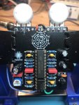
Ok, so my last two builds have been a little more challenging than usual. With this one, I was extra cautious—I verified each resistor and cap to verify I was grabbing the correct ones. I am pretty confident those are correct. Of course, I could totally have overlooked something, so any catches will be much appreciated. Here is what I have done so far:

  • I am getting what appear to be proper voltages on the TL072 and the HT8950.
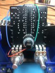
  • When I trace the signal, it craps out just after the 1M variable resistor where it connects to R2.
  • I am getting a clean signal on Pin 2 of the TL072, but no output on Pin 1.
  • I have swapped out the TL072 a couple times, just to be sure.
  • When I probe the center pin on the variable resistor, the signal is weak, slightly distorted, and there is a high-pitched squeal present.
  • I have tried measuring and moving the VR and it appears to be "working" in the sense that I can see the resistance change within expected ranges. Yet, there seems to be something amiss in that area of the circuit.
Before I replace that VR, I wanted to see if anything obvious jumps out to anyone. I know it's not a boxed variable resistor, but I believe the pinout should be the same, correct?
 

Attachments

  • IMG_4477.jpg
    IMG_4477.jpg
    816.2 KB · Views: 19
  • IMG_4475.jpg
    IMG_4475.jpg
    786.8 KB · Views: 18
is that the correct rotary switch? should be 2 pole 4 terminal. I ask because it looks like the positions around the outside are numbered up to 8.
 
Hm, I just checked my order and I did order the 2P4T, and it only has 4 clicks when I turn it, so I am guessing it is? I mean, I wouldn't put it past me to order the wrong one, either. :) Thanks for the suggestion, though!
 
4 clicks should be right, as verified by your order.

for you !M trim pot, are you able to adjust is so that you have 0 resistance between the C1 and R2? when you have it set at 0 resistance, what resistance do you measure between pin 1 and pin 2 of the TL072? If R2 is the correct value, you should then have about 27K resistance between those two pins.

similarly, if you turn the trimpot all the way in the other direction, check the resistance between pin 1 and pin 2 to see if you are getting 1M + 27K resistance.
 
Back
Top