okstateblues
Active member
Looking to finish a Benson build and need some assistance. I have 2N5485's and just want to double check that they will work if installed according to the silkscreen on the board. Any feedback would be greatly appreciated.


These are a regularly stocked item now:
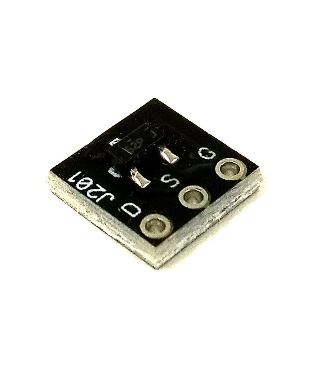
J201's are available in SMD - MMBFJ201. So why even bother with substitutes?")
These are a regularly stocked item now:
For these boards (or any SMD transistor footprint), apply a small amount of solder to the pad for the gate. With an ESD tweezers, place the SMD J201 into position while the solder is heated on the gate pad. Wait 30 seconds. Heat the pad and lead for one of the other leads and apply a small amount of solder. Wait and repeat. Then, reflow the gate pad/lead to ensure good connection between the device and pad.
cool. Just curious (if you care to share), are you hand soldering these, or ordering them re-flowed from a shop?

This is the method I use, makes it super easy. Also, using blue tack to hold the board in place while soldering is extremely helpful and makes the process much less frustrating.For these boards (or any SMD transistor footprint), apply a small amount of solder to the pad for the gate. With an ESD tweezers, place the SMD J201 into position while the solder is heated on the gate pad. Wait 30 seconds. Heat the pad and lead for one of the other leads and apply a small amount of solder. Wait and repeat. Then, reflow the gate pad/lead to ensure good connection between the device and pad.