9v Power Jack - Small, No Third Pin, OUTTIE.

Does anyone have a source for a 9V power jack that fastens from the outside? By *small* I mean not one of the switching kinds. Something like this but with the nut on the outside:

Example

Side note: I can't for the life of me understand why the majority (that I am able to find) seem to fasten from the inside, meaning that if you want to remove the PCB you have to unsolder the power jack. Surely I'm not the only one who cares about this?
I completely agree and think that every time I am assembling but have just gotten used to using the ones you linked. But I would love to know if anyone sells a small external nut power jack.
 
I would entertain that. Any recommendations come to mind?

It can be a bit involved making them yourself—totally doable for one-offs or occasional use—but more work than simply soldering them. You have options: SBE sells preassembled connectors and the female headers as well as the parts to make your own. Other parts suppliers have them too. With the headers in particular, confirm pitch with the board pad spacing and clearance with the rest of the build elements. Many production units use these; they’re great for testing before you commit to final wiring.

Application:
You would leave the power jack and the wire assembly in the enclosure, but can remove the assembly from the female connector and remove the board from the enclosure without desoldering. You can then plug a breadboard-mounted male wire assembly into the board-mounted female header if needed for troubleshooting. Note that these can be used for any offboard wires you’d like.

LINK: https://smallbear-electronics.mybigcommerce.com/search.php?search_query=molex
 
I use the big outties, but use 2 nuts and thread em back closer to the inside so the outtie part doesn’t stick out so much.

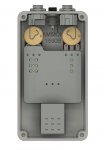
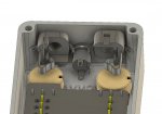
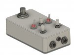
I use those too, which are readily accessible. My *current* mission, and which I believe I have solved, is to package all this stuff in a 1590B enclosure, which is smaller than the standard 125B enclosure that PedalPCB seems to frequently design for. When you have the input/output jacks come out the top, in the (smaller) 1590B enclosure, there is no room for a bigger power jack (i.e., the kind that switches). There just isn't enough real estate. But if you stick to the smaller kind, and with careful placement, it fits. Like this:


1.jpg

2.jpg

3.jpg

4.jpg
 
I second that, very nice modeling.

A very tight fit. What's the order of assembly?
1) pots & toggle switches
2) jacks
3) board
4) final wiring

Is it possible to disassemble for rework or troubleshooting after that?

To quote my mentor, Arpad Pallai... "If it's doable, somebody will do it."
 
There is a good reason that the 125B enclosure is used for a lot of these builds, since has a lot more room for less precise placements. I think there is an elegance to having a tight layout using the 1590B enclosure, but it would create problems for folks trying to sub in larger parts or dealing with less precise drilling. It can be an aspirational goal. : ^)
 
I second that, very nice modeling.

A very tight fit. What's the order of assembly?
1) pots & toggle switches
2) jacks
3) board
4) final wiring

Is it possible to disassemble for rework or troubleshooting after that?

To quote my mentor, Arpad Pallai... "If it's doable, somebody will do it."

I'll know more in a week when I have the enclosure and machine it, but my guess will be:

1. PCB with pots and toggle switches mounted, with jacks wired in a floating state.
2. Insert PCB with pots/toggle switches, leaving jacks floating outside.
3. Insert ouput jack. This should be straightforward.
4. Insert input jack, but rotated 90 for clearance, then once in, rotate it back. In the screenshot above you can see the conflict with the pot.
5a. Plug the power jack in with connectors (if I can't find the jack I want). or
5b. Insert power jack into enclosure from inside, fasten nut from outside (if I can find the jack I want).
 
There is a good reason that the 125B enclosure is used for a lot of these builds, since has a lot more room for less precise placements. I think there is an elegance to having a tight layout using the 1590B enclosure, but it would create problems for folks trying to sub in larger parts or dealing with less precise drilling. It can be an aspirational goal. : ^)

True. FWIW, I grew up as a CNC machininist, so I'm doing this on a machine. That's why I CAD it first. But if you look at the screenshots, outside tall electrolytic caps, there doesn't seem to be much conflict with subbing in larger parts the only real potential for conflict is the lid, which is pretty far away.

I have now I think 10 PedalPCB boards, and a couple are 2.250" wide and one is 2.350" wide (the Angry Charles I think). These will not fit inside the 1590B enclosure without some clearance milling on the inside of the box. The good news is there is enough wall thickness for these to fit as well.

What I can't fit is a 9volt battery, which I kind of want. And even if I could, the switching jack won't fit on the top, and I specifically want it on the top because I read elsewhere on this forum that it is not possible to fit jacks and the power jack on the top of a 1590B enclosure. I think you can.

I am pursuing the 1590B box for no reason other than I think it looks cool.
 
Does anyone have a source for a 9V power jack that fastens from the outside? By *small* I mean not one of the switching kinds. Something like this but with the nut on the outside:

Example

Side note: I can't for the life of me understand why the majority (that I am able to find) seem to fasten from the inside, meaning that if you want to remove the PCB you have to unsolder the power jack. Surely I'm not the only one who cares about this?
I too hate this.
 
I just leave the power leads a little longer. I don't like the appearance of the nut on the outside.
Good point, I hadn't fully thought that through. For what it's worth, I bought the connectors from Amazon mentioned in a previous post, and we'll give them a try. Meanwhile I will keep looking for my unicorn power jack, LOL.
 
Since you’re adept at CAD and design, I would maybe suggest another route:

If you design an I/O daughter board for the 1590B builds with top-mount jacks, you could have a DC jack soldered to the board along with the I/O jacks. That way, you don’t even have to worry about mounting the DC jack. The DC jack would be accessible via a hole and secured with the nuts on the I/O jacks.

You’d have to sort out the spacing (and might have to mount the DC jack on the underside), but it could work for you.
 
Back
Top