Adding a blend to a Promethium (HM-2)

That's fine. If I were to do it over again, I would use a very different circuit, though.
Adding a clean blend needs to be considered on a pedal-by-pedal basis because a lot of circuits flip the phase.
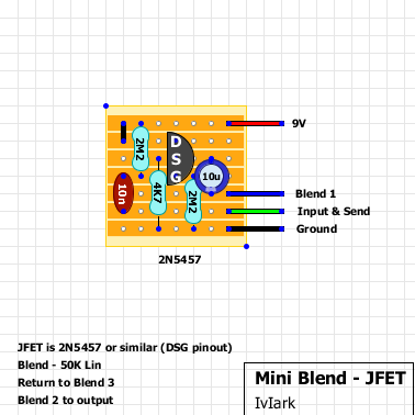
I made my own clean blend on perf that includes a phase switch. This is ideal then you can use it with any pedal. It is similar to the Paramix. I have a monster multipedal in the works that is an hm-2 style pedal, 8 way clipping diode switch, clean blend with send/return insterts, and a muzzle. It's a beast. I started working on adding a boost to the clean signal but then I got side tracked fixing my amp and causing drama with tube amp corksniffers on another forum. Finally fixed it today so back to the pedal I suppose.
Muzzle -> Blend->Hm-2(murdock plus) Aint much to look at yet but it is a WIP.

multi-pedal.jpg
 
Man my head has been all over the place but I'm pretty sure It doesn't matter where the ground is connected in terms of jack vs promethium as long as he is tapping the +9 after the protection diode on the promethium.
And the filter cap. Don't forget that. ;)
 
And the filter cap. Don't forget that. ;)
Yep, the cathode of the protection diode should be at a node with the cap though so anything apart of that net is good.

Well as far as functionality, it seems to works seem less.
No extra noise or any of that unwanted jazz
It might work fine but if you accidentally plug the wrong plug into the pedal you could have a blown power supply or worse. You might be telling yourself "Nah I would never do that." That's how I felt too but let me tell you it happens and will probably happen to you at some point.
 
I think the analogman site may have a listing of pedals and circuit topology that are known phase flippers.
@jubal81 Would you mind explaining why you went this route over just making a resistor-based voltage divider? I'm interested as I have no experience using the TLE2426.
 
It's this guy right here. You can see the 9v (VCC) supply rail and the 4.5v. (VREF). This is a circuit block that is common, for the most part, to lots of these pedals. It's just the power plant for effects supplying whatever a particular circuit block or element needs, (9v+, 18v+, 9v-, 4.5v+ or -, etc). You can figure out what kind of power supply is being fed into a circuit block by paying attention to those little flags (VCC, VREF, etc).

I suspect you want to tap the 9v rail, but again, out of my depth.
View attachment 19986

@fractal33, his offboard buffer will probably have a 9v+ and a ground coming off of it. Wouldn't he want to take power off the 9+ rail and elevate the ground by attaching it to the negative rail? Have I got that right?

The buffer he's describing probably works a lot like PedalPCB's simple JFET buffer:
View attachment 19988
So if I was to wire it appropriately in this fashion, where on this circuit am I hitting?
Just the VCC and VREF points?
 
Yep, the cathode of the protection diode should be at a node with the cap though so anything apart of that net is good.


It might work fine but if you accidentally plug the wrong plug into the pedal you could have a blown power supply or worse. You might be telling yourself "Nah I would never do that." That's how I felt too but let me tell you it happens and will probably happen to you at some point.
And blown power supply for the circuit or for my actual isolated power supply? (Walrus Phoenix)
 
@delackattack If I were dropping a simple Jfet buffer into the board, I'd probably solder the + and gnd to each side of either C23 or I'd tap the appropriate legs of the ICs (pins 4 and 8). But I'd defer to more experienced builders. The VCC and VREF locations aren't actually a place. They are a reference for reading the schematic.
 
Last edited:
So, this the second Promethium that I have added this SFB circuit to and now the pot acts as it’s reversed and there is NO blend only acting as a level.
Maybe I goofed on the circuit but I’ve checked my connections with a multimeter and everything seem okay but lug one and two on the pot are getting a matching signal.
 

Attachments

  • image.jpg
    image.jpg
    1.2 MB · Views: 3
Update: Plugged pedal up with the circuit connected to probe and smoke started to come from the circuit.
I’ve wired it up back without the blend circuit and it sounds as usual so I’m going to build a new SFB and try again.
😢
 
Update: Plugged pedal up with the circuit connected to probe and smoke started to come from the circuit.
I’ve wired it up back without the blend circuit and it sounds as usual so I’m going to build a new SFB and try again.
😢
Hope you didn't let the magic smoke out. That's a bummer. Was a component in backwards? Were you using the audio probe on the signal path or was it touching source voltage. What component was smoking, btw?

Maybe post a drawing of what precise modifications you were attempting to the circuit. With a thing like this, it would be really valuable for you and others to know exactly why the magic smoke showed up.

And if you decide to attempt another experiment here then this seems like one of those projects that you could easily fly in your modification ideas from a breadboard. As I think about it, it might even be cool for you to experiment with panning vs blending.
 
Last edited:
Hope you didn't let the magic smoke out. That's a bummer. Was a component in backwards? Were you using the audio probe on the signal path or was it touching source voltage. What component was smoking, btw?

Maybe post a drawing of what precise modifications you were attempting to the circuit. With a thing like this, it would be really valuable for you and others to know exactly why the magic smoke showed up.

And if you decide to attempt another experiment here then this seems like one of those projects that you could easily fly in your modification ideas from a breadboard. As I think about it, it might even be cool for you to experiment with panning vs blending.
I’m not sure as to what exact component was smoking but I just unplugged it as quickly as I saw it.
 

Attachments

  • image.jpg
    image.jpg
    1.3 MB · Views: 2
  • image.jpg
    image.jpg
    1.3 MB · Views: 2
Hope you didn't let the magic smoke out. That's a bummer. Was a component in backwards?

I’m not sure as to what exact component was smoking but I just unplugged it as quickly as I saw it.
Sorry, I can't sort all that out. So the buffer circuit was the thing that was smoking? Where on the schematic did you fly in the wires of the buffer. I am having a hard time tracking the 9 wires coming off of it, which seems excessive. It's a simple Jfet buffer circuit, I'd think it would have a input, output, 9v and ground. What do the other wires do?
jfet.png
 
Last edited:
I’m not sure as to what exact component was smoking but I just unplugged it as quickly as I saw it.
My mistake. You aren't adding a simple Jfet buffer, you are adding a blend circuit. And it's EffectsLayouts board so of course there's no schematic (I hate those guys for that. Schematics tell the story).

They recommend using a J201 Jfet and their wiring scheme assumes a D-S-G pinout. What did you actually use? (And J201s are pretty unobtanium right now, if that's what you used, how confident are you that it is authentic? How did you measure it?) It also appears that there is a 10uf cap after the Jfet and their drawing makes it appear to be an electrolytic.

I don't really understand their layout (why are they linking the "in" and the "Send." That seems weird. And the way the pot is wired, it appears to be panning and not blending, but the confusing thing is that nothing is being dumped to ground. And the biasing on the drain looks sketchy. If you hook this circuit up to a breadboard and put 9 volts to it, what voltage do you get at the drain vs. the gate. I guess I don't really understand how your EffectsLayout tagboard actually works. Here's a PCB that actually blends two signals. Not so say that one is better than the other, its just that I can look at the schematic and see that it makes sense to me. Without a schematic, the EffectsLayout board just looks like gibberish to me.

 
I actually used a 2n5457 instead on both circuits I’ve made.
The first is still completely operational and the second one has been a dud so far.
This is the one I just made with a Fairchild J201
 

Attachments

  • image.jpg
    image.jpg
    1.1 MB · Views: 1
  • image.jpg
    image.jpg
    1.1 MB · Views: 1
I actually used a 2n5457 instead on both circuits I’ve made.
The first is still completely operational and the second one has been a dud so far.
This is the one I just made with a Fairchild J201
That thing looks like it would be easy to connect to a breadboard. When you put 9v to it, what readings do you get on the drain and the gate?
And as a practical matter, maybe check continuity everywhere and make sure some solder hasn't dripped somewhere where it isn't supposed to be.

And a best practices thing that I'm sure you already know, but I would socket sensitive components (Jfets, ICs, etc). I just wouldn't ever put heat to them (though I'm sure they can mostly take it). And in your specific case, I'd socket the 4.7k resistor as well. That's a bias resistor and the value may have to change.

 
Last edited:
Also I had just noticed the side with Return/ out/ 9+ was in the wrong slots
I would work one problem at a time. You need to find out why you got smoke and, more importantly, did the smoke damage something. I'd isolate it on a breadboard and check voltages first. When you are sure in your mind that the Jfet is ok, then I'd start worrying about how to fly it into the existing circuit.

(So does that mean you were running 9v to one of the pot lugs?)

PS: Your particular blend circuit is explained in Post #21. Here's a schematic to it:
seanm.ca minblend   FET.png

And here's some discussion about it where the author says use only Linear pots:
 
Last edited:
I am pretty sure I was running it to a pot lug.
I wired a new one into the pedal but now I’m coming across the same issue.
Volume all the way with the blend is at zero, kind of a mix at 50 percent and dead silent when I max the blend.
I’ve also wired it both to the C23 cap and the DC jack.
I’m having my guitarist bring my first one back so I can re examine what I did or didn’t do to get to work on my first try.
 
Back
Top