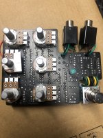
Sure, status LEDs lighting/not lighting is information, but can also be the result of issues totally unrelated to the signal and it's processing in the circuit (i.e.: a burnt out LED, bad solder on the 3pdt switch, etc). Other than power supply, it's not directly relevant to the main circuit and won't tell you anything about issues in signal processing there--whether it works or doesn't work doesn't affect anything at all. Proof is I've stopped putting LEDs in 90% of my builds because it's my least favorite part of building until I audition the pedal as a keeper. Obviously this doesn't apply to LEDs within an LED/LDR array that are functional in LFOs or what have you.
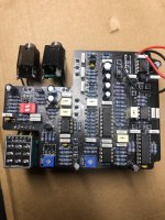
@BrainDrain if you suspect a problem with current, then you can plug the pedal in, connect one end of your multimeter to a pedal ground, and probe and write down all voltages at the IC and transistor pins (since you've already done the jack and diode). If you publish them here, folks will be able to tell you if it looks right or there's an issue.
[edit: sorry, was writing and didn't see your reply above]