SOLVED Blue Sheep No Effect

joelorigo

Well-known member
I'm testing my in-progress Blue Sheep in my Auditorium Test Platform, I am getting a bypass signal, but when switching to Active, there is a "pop" but then no signal. I have continuity between the Test Platform and the PCB on all the connections, I don't see any solder bridges and the Platform was working earlier when I tested another circuit. Can someone take a look?
 

Attachments

  • IMG_7215.jpg
    IMG_7215.jpg
    412.7 KB · Views: 89
  • IMG_7214.jpg
    IMG_7214.jpg
    466 KB · Views: 86
Yep. I previously had tired this with the SW cable connected to the test platform. Now that it is disconnected, I tried the spots that didn't get any signal before and they are all getting it now. The I tried the next spots in the schematic and they are also, then in & out pins on the 2nd IC and there is signal, and so on, and all points are getting signal including the OUT screw on the test platform.
 
Wait, now I am getting signal when in Active. SW still disconnected. An hour and a half ago that was the buzz hum sound. As it was previously in the thread. WTF is gong on???
 
Last edited:
Yeah, I'm happy that it is working but I don't understand why suddenly it is. Nothing was done between earlier where there was buzz and now except using the audio probe.

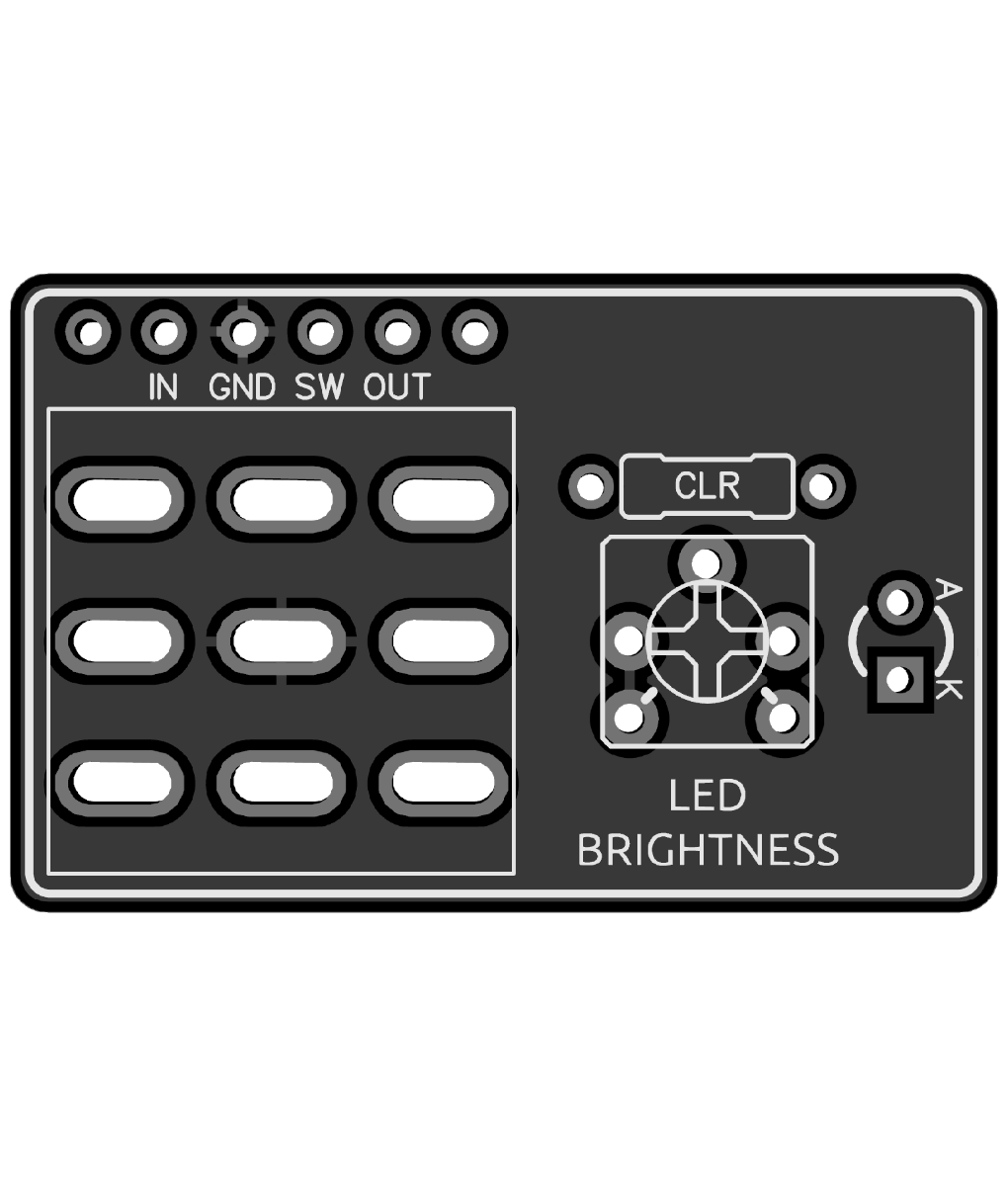
Sooooo, about the LED. Normally after using the test platform I wire it up in the enclosure, but that has only been with PedalPCB boards which have the LED pads.
I have a PedalPCB 3PDT breakout board with the LED pads soldered to a footswitch already. Do I disconnect all the rest of wires at the bottom of the test platform and attach them to the daughter board? Would that work the way the test platform is constructed?
 
Thanks zgrav.
With this Blue Sheep PCB, the SW pad is +9v so you connect that to a wire with CLR (resistor) to the Anode on the LED.
The Cathode side of the Led connects to a wire to the PedalPCB footswitch SW pad.
This Blue Sheep design is for a Footswitch PCB with CLR & LED on board !
 
Last edited:
Wait, now I am getting signal when in Active. SW still disconnected. An hour and a half ago that was the buzz hum sound. As it was previously in the thread. WTF is gong on???
There could be a cold solder joint or a piece of solder that is floating around on the board & when you knocked or move it, it corrected itself???
 
Thanks zgrav.
With this Blue Sheep PCB, the SW pad is +9v so you connect that to a wire with CLR (resistor) to the Anode on the LED.
The Cathode side of the Led connects to a wire to the PedalPCB footswitch SW pad.
This Blue Sheep design is for a Footswitch PCB with CLR & LED on board !
I already have a breakout PCB soldered to a footswitch but I should do this with a loose footswitch? And lug 4 is the SW one on a footswitch, right?

Is it advisable to test the LED first before putting it all in the enclosure?
 
Is the pedal now working as a finished troubleshoot?
Excellent question. If not, then no point mucking around with the LED. @joelorigo is your pedal working now? I thought it was, but I read your last few posts again and now I’m not so sure. Are you getting intermittent sound with the effect engaged? Or is the pedal working as intended?

If it’s good and you’re boxing it up, I’d really urge you to wire the footswitch up without a breakout board. Take your time and don’t overheat the lugs. I love the convenience of breakout boards, but they can make troubleshooting a real pain. Also it’s good to understand how the switch works!
Yeah it’s magically working even though ultimately all that was done to it was a bunch of audio probing, continuity testing and taking the ICs in and out.

I have done a good number of footswitches without breakout boards so I get it (more or less). I already have one soldered to a footswitch so I might as well use them.

I am just unclear how to proceed with testing the LED before assembly as it is still attached to the test platform (minus the SW wire as indicated above obviously).

Do I unhook the rest of bottom wires (IN OUT and GND) and use them to wire up a new footswitch with the LED/CLR as described above? Or leave the wires as they are and just hook up the SW wire?
 
Last edited:
Yeah it’s magically working even though ultimately all that was done to it was a bunch of audio probing, continuity testing and taking the ICs in and out.

I have done a good number of footswitches without breakout boards so I get it (more or less). I already have one soldered to a footswitch so I might as well use them.

I am just unclear how to proceed with testing the LED before assembly as it is still attached to the test platform (minus the SW wire as indicated above obviously).

Do I unhook the rest of bottom wires (IN OUT and GND) and use them to wire up a new footswitch with the LED/CLR as described above? Or leave the wires as they are and just hook up the SW wire?


EDIT: Oh sorry, I missed that part where you say if it’s working there’s no point in mucking around with the LED.
All you have to remember that on this PCB, the SW pad is POWER and it has to go to the Anode + side of the LED.
The Cathode - to centre top lug of the Footswitch, The Current limiting resistor can go on + side or - side of Led, it will still work!

Simply put, your issue on the Test platform is the led wiring is reversed which caused the short coz power went to Ground.

LED Wring.jpg
 
Last edited:
All you have to remember that on this PCB, the SW pad is POWER and it has to go to the Anode + side of the LED.
The Cathode - to centre top lug of the Footswitch, The Current limiting resistor can go on + side or - side of Led, it will still work!

Simply put, your issue on the Test platform is the led wiring is reversed which caused the short coz power went to Ground.

View attachment 56411

Apologies for the gnarly job on that switch … also for others’ benefit, no need to use a 1/2 watt resistor. That was just the first one I grabbed.

Also possibly worth noting for whomever might run across this: we talk about the 3pdt turning the pedal “off” or “on” but that’s just convenient shorthand and not entirely true lol. As wired here If the board is plugged in, it’s getting power and is “on”. When engaged, the switch simply completes the circuit to let the jacks talk to the board and make groovy sounds. When in bypass, the in and out jacks are connected directly, bypassing the board, disconnecting the LED, and sending the effect input to ground.
 
All you have to remember that on this PCB, the SW pad is POWER and it has to go to the Anode + side of the LED. The Cathode - to centre top lug of the Footswitch,
Is that different from the PedalPCB boards then?
The Current limiting resistor can go on + side or - side of Led, it will still work!

Simply put, your issue on the Test platform is the led wiring is reversed which caused the short coz power went to Ground.
Do I have to do anything different than the usual when using one of these, which is what I was intending?
 
Back
Top