I recently got my prototype DIY build of a MIJ DS-1 going, and noticed two things:
1) It is a LOT thicker than any post-1994 DS-1 I've owned. So much so that I'm looking at reducing one of the coupling caps to make it a bit leaner. I mean, dialed in right, it's competing with a Metal Zone (in a good way) in terms of being a big, tight distortion.
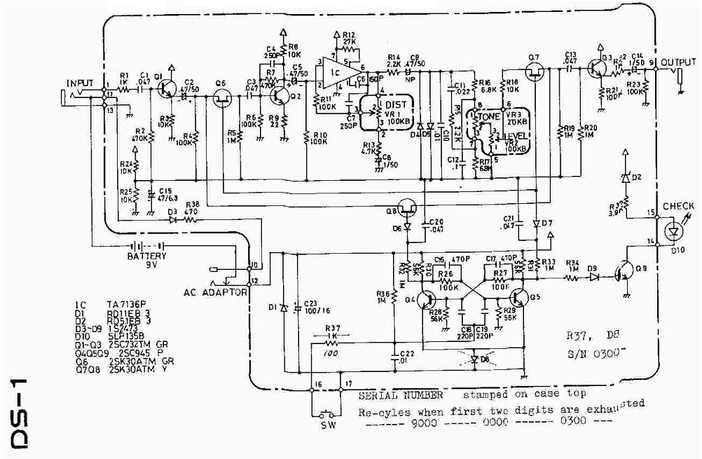
2) Yes, that Q2 transistor boost is SLAMMING the preamp in the classic DS-1 fashion. I've tried selecting transistors with lower HFE (I have all three in the 250-270 range), but I can't keep doing that. After researching the Q2 boost, it seems like the only other option is to change the values of R6/R9 to lower the boosting.
I'm using an ECG1464 (7pin preamp) for the IC, 2SC732TM-GR & 2SC2240-GR transistors and 1S1588 diodes. I removed the JFET switching section and the diode/resistor for the ACA adapter, but left the input/output buffers.
Question: It seems that 'GR-level' transistors (i.e. in the 200-400 hfe range) are standard for this and the SD-1. Is modifying R6/R9 pretty much the best way to adjust the DS-1's Q2 boost? And should I just disregard trying to select lower-hfe transistors if they're already in the 'GR' range?
I've read that Jack Ormans DS-1 'Fat Mod' for R6/R9 reduces the boost level, but is too much of a reduction.
I'll see if I can post pics of my layout tonight.
thx
1) It is a LOT thicker than any post-1994 DS-1 I've owned. So much so that I'm looking at reducing one of the coupling caps to make it a bit leaner. I mean, dialed in right, it's competing with a Metal Zone (in a good way) in terms of being a big, tight distortion.
2) Yes, that Q2 transistor boost is SLAMMING the preamp in the classic DS-1 fashion. I've tried selecting transistors with lower HFE (I have all three in the 250-270 range), but I can't keep doing that. After researching the Q2 boost, it seems like the only other option is to change the values of R6/R9 to lower the boosting.
I'm using an ECG1464 (7pin preamp) for the IC, 2SC732TM-GR & 2SC2240-GR transistors and 1S1588 diodes. I removed the JFET switching section and the diode/resistor for the ACA adapter, but left the input/output buffers.
Question: It seems that 'GR-level' transistors (i.e. in the 200-400 hfe range) are standard for this and the SD-1. Is modifying R6/R9 pretty much the best way to adjust the DS-1's Q2 boost? And should I just disregard trying to select lower-hfe transistors if they're already in the 'GR' range?
I've read that Jack Ormans DS-1 'Fat Mod' for R6/R9 reduces the boost level, but is too much of a reduction.
I'll see if I can post pics of my layout tonight.
thx